NPM-D3维修手册.pdf - 第54页
NPM-D3 SERVICE MANUAL 4.2 XY Drive Axes Page 4-16 EJM6D3-MB-04SM-02.DOC 4.2.4 Cableveyor Replacement ケーブルベア交換 电缆支架的交换 Unit No. N610052923AA N610052924AA 4.2.4 Cableveyor Replacem ent ケーブルベア交換 电缆支架的交换 X-axis Cableveyor …
NPM-D3
SERVICE MANUAL
4.2 XY Drive Axes
EJM6D3-MB-04SM-02.DOC Page 4-15
4.2.3 Y-axis Interference Photo-sensor Adjustment
Y 軸干渉 PH の調整
Y 轴干涉 PH 的调整
Unit No.
N610052923AA
4.2.3 Y-axis Interference
Photo-sensor Adjustment
Y
軸干渉
PH
の調整
Y
轴干涉
PH
的调整
Y-axis Interference Photo-sensor Adjustment
Y 軸干渉 PH の調整
Y 轴干涉 PH 的调整
3.
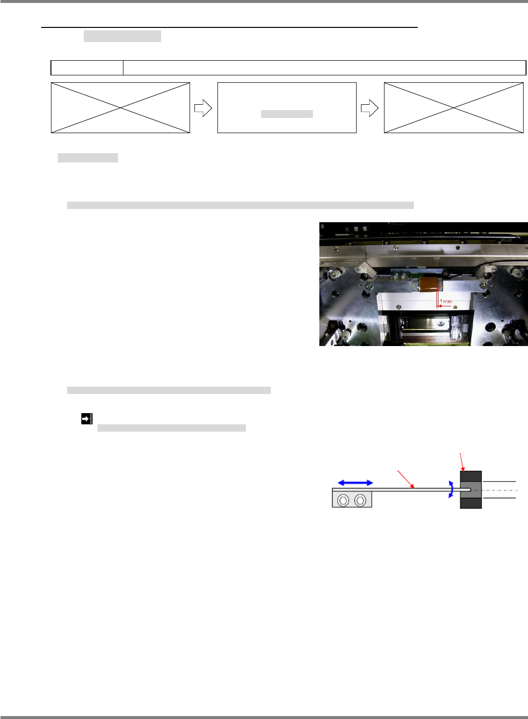
1. Bring the front and rear side beams near to each other by hand so that the clearance between their
respective mechanical stoppers is 1 mm.
FRONT 側ビームと REAR 側のビームを手で近づけ、FRONT 側メカストッパと REAR 側メカストッパのすき間を 1 mm にします。
用手将 FRONT 侧轴和 REAR 侧轴靠近,并使 FRONT 侧的机械止动器和 REAR 侧的机械止动器之间的间隙调整为 1 mm。
2. Adjust the position of the interference sensor dog so that the interference photo-sensor turns ON in this
situation.
このとき、干渉 PH が ON するように干渉センサ DOG の位置を調整します。
此时,为了使干涉 PH 置于 ON,调整干涉传感器 DOG 的位置。
Clearance between front and rear side mechanical stoppers: 1 mm
FRONT
メカストッパと
REAR
メカストッパのすき間
:
FRONT
机械止动器和
REAR
机械止动器之间的间隙
:
Fig. 1
Fig. 2
Y-axis interference dog
Y-axis interference sensor
NPM-D3
SERVICE MANUAL
4.2 XY Drive Axes
Page 4-16 EJM6D3-MB-04SM-02.DOC
4.2.4 Cableveyor Replacement
ケーブルベア交換
电缆支架的交换
Unit No.
N610052923AA
N610052924AA
4.2.4 Cableveyor Replacement
ケーブルベア交換
电缆支架的交换
X-axis Cableveyor Replacement
X 軸ケーブルベアの交換
X 轴电缆支架的交换
4.
1. Turn OFF the power and air.
電源・エアーを OFF にします。
将电源和空气置于 OFF。
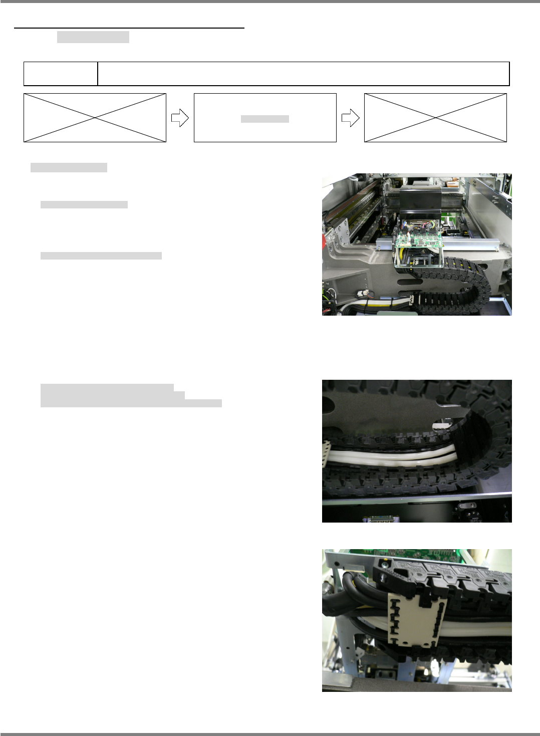
2. Detach the top rear cover from the head. (Fig. 1)
ヘッド上部後方のカバーを外します。(Fig. 1)
拆下头上部后方的盖。(Fig. 1)
3. Detach all inside cableveyor covers. (Fig. 2)
Cut the cable ties that lock the inside cableveyor covers to the cable anchor plate, and detach the inside
cableveyor covers. (Fig. 3)
ケーブルベアの内側の蓋を全て外します。(Fig. 2)
ケーブルベア内側蓋と、ケーブル固定板を止めている
インシュロックを切り、ケーブルベアの内側蓋を外します。(Fig. 3)
拆下电缆支架内侧的全部盖。(Fig. 2)
切断固定电缆支架内侧盖和电缆固定板的捆束带,拆下电缆支架内侧的盖。(Fig. 3)
Fig. 1
Fig. 2
Fig. 3
NPM-D3
SERVICE MANUAL
4.2 XY Drive Axes
EJM6D3-MB-04SM-02.DOC Page 4-17
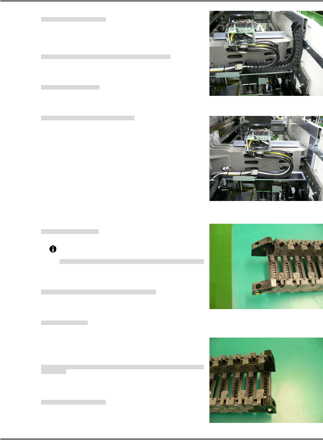
4. Remove the bolts that lock down the cableveyor.
ケーブルベアの固定ボルトを外します。
卸下电缆支架的固定螺栓。
5. Cut the cable ties that lock the outside cableveyor covers and
cable anchor plate together.
ケーブルベア外側蓋とケーブル固定板を止めているインシュロックを切ります。
切断固定电缆支架外侧盖和电缆固定板的捆束带。
6. Detach the cableveyor. (Fig. 4, Fig 5)
ケーブルベアを外す。(Fig. 4, Fig. 5)
卸下电缆支架。(Fig. 4, Fig. 5)
7. Wrap new cable ties around the cable anchor plate.
ケーブル固定板に新しいインシュロックをセットします。
在电缆固定板上设置新的捆束带。
8. Set a new cableveyor.
新しいケーブルベアセットします。
设置新的电缆支架。
Note that the cableveyor ends differ in installation
configuration. (Figs. 6 and 7)
ケーブルベア両端形状は、取り付け側により異なるので注意してください。
(Fig. 6, Fig. 7)
电缆支架两端的形状,由于安装侧有所不同,敬请注意。
(Fig. 6, Fig. 7)
9. Lock the cableveyor outside covers and the cable anchor
plate together with the cable ties.
ケーブルベア外側蓋とケーブル固定板をインシュロックで固定します。
用捆束带固定电缆支架外侧盖和电缆固定板。
10. Anchor the cableveyor.
ケーブルベアを固定します。
将电缆支架固定住。
11. Attach the inside covers to both ends of the cableveyor, lock
to the cable anchor plate using the cable ties and attach the
remaining covers.
ケーブルベア両端の内側蓋を取り付け、ケーブル固定板とインシュロックで固定し、残りの蓋を全て
取り付けます。
安装电缆支架两端的内侧盖,将其用捆束带和电缆固定板固定住后,安装剩下的全部盖。
12. Attach the top rear cover to the head.
ヘッド上部後方カバーを取り付けます。
安装头上部后方盖。
Fig. 4
Fig. 5
Fig. 6
Head anchor side
Fig. 7
Beam anchor side