NPM-D3维修手册.pdf - 第192页
NPM-D3 Service Manual 5.5 Light Weight 16-Nozzle Hea d Page 5-64 EJM6D3-MB-05SM-00( 編集中 ).DOC Fig. 1 Connecto r 5.5.6 Z-axis Linear Motor Detaching / Attaching Z 軸リニアモータの取り外し / 取り付け Z 轴线性电机的拆卸 / 安装 Unit No. N610096433AA …
NPM-D3
Service Manual
5.5 Light Weight 16-Nozzle Head
EJM6D3-MB-05SM-00(
編集中
).DOC Page 5-63
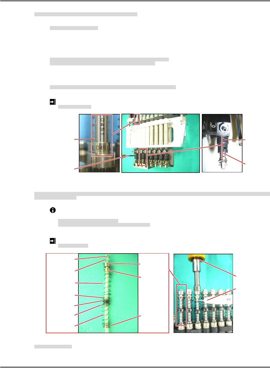
14. Insert the nozzle holder
positioning into the holder and perform positioning of the holder. (Fig. 14)
ホルダにノズルホルダ
規正を挿入し、ホルダの位置決めをします。
(Fig. 14)
将吸嘴支架的
定位工具插入支架中,进行支架的定位。
(Fig. 14)
①
Face the markings on the shafts outwards.
シャフトの刻印を外向きにします。
要使轴的刻印朝外。
②
Insert the nozzle holder
positioning into the eight nozzle holders and lightly tighten the lock screw
of the holder.
Make sure that the marking of the ball spline, lock screw of the holder and vertical groove are facing
the front side.
ノズルホルダ
規正を
8
本のノズルホルダに挿入し、ホルダの止めねじを仮締めします。
ボールスプラインの刻印とホルダの止めねじ、縦溝が正面を向いていること。
将吸嘴支架
定位工具插入
8
根吸嘴支架中,临时固定住支架的固定螺丝。
滚珠花键的刻印和支架的固定螺丝、纵沟都要朝向正面。
③
Detach the nozzle holder
positioning and securely tighten the lock screw (2-M2.5x3) of the holder
with a torque driver.
ノズルホルダ
規正を外し、ホルダの止めねじ
(2-M2.5 x 3)
をトルクドライバで本締めします。
取下吸嘴支架
定位工具,用扭矩螺丝刀将支架的固定螺丝
(2-M2.5 x 3)
正式拧紧。
Lock screw tightening torque: 30
3 N
cm
止めねじ締め付けトルク
固定螺丝的拧紧扭矩
15. Insert the collar, spring, washer and guide carefully not to let the spring fly off, and insert the quenched pin
(
1.6 mm) into the hole of the shaft to stop turning, then tighten the nut with a torque driver.
スプリングを飛ばさないように注意して、カラー、スプリング、ワッシャ、ガイド、ガイドを入れ、焼入れピン
(
1.6 mm)
をシャフトの穴に挿入して回り止めとし、ナットをト
ルクドライバで締め付けます。
在注意不要使弹簧跳掉的同时,放入轴环、弹簧、垫圈、导向环,将淬火销
(
1.6 mm)
插入轴的孔中进行止转,然后用扭矩螺丝刀拧紧螺母。
Make sure that the bearing and collar are orientated properly.
Insert the quenched pin (
1.6 mm) into the hole of the shaft to stop turning it.
ベアリング、カラーの向きに注意すること。
シャフトの周り止めには必ず焼入れピン
(
1.6 mm)
を使用すること。
请注意轴承、轴环的朝向。
对轴的止转必须使用淬火的销
(
1.6 mm)
。
Nut tightening torque: 80 N
cm
ナット締め付けトルク
螺母拧紧扭矩
16. Attach the
unit.
ユニットを取り付けます。
装上
装置。
‘5.5.3
Unit Detaching / Attaching’.
Fig. 14
Vertical
groove
Marking
Lock screw
Torque drive
r
Fig. 15
Nu
t
Bearing
Collar
Spring
Spring
CollarWashe
r
Guide
Washe
r
Torque driver
Quenched pin
Washe
r
NPM-D3
Service Manual
5.5 Light Weight 16-Nozzle Head
Page 5-64 EJM6D3-MB-05SM-00(
編集中
).DOC
Fig. 1
Connecto
r
5.5.6 Z-axis Linear Motor Detaching / Attaching
Z
軸リニアモータの取り外し
/
取り付け
Z
轴线性电机的拆卸
/
安装
Unit No.
N610096433AA
5.5.1 Z-axis Control Board
Detaching / Attaching
Z
軸コントロール基板の取り外し
/
取り付け
Z
轴控制基板的拆卸
/
安装
5.5.6 Z-axis Linear Motor
Detaching / Attaching
Z
軸リニアモータの取り外し
/
取り付け
Z
轴线性电机的拆卸
/
安装
5.5.1 Z-axis Control Board
Detaching / Attaching
Z 軸コントロール基板の取り外し / 取り付け
Z
轴控制基板的拆卸
/
安装
27.
1. Detach the Z-axis control board.
Z
軸コントロール基板を取り外します。
拆下
Z
轴控制基板。
‘5.5.1 Z-axis Control Board Detaching /
Attaching’.
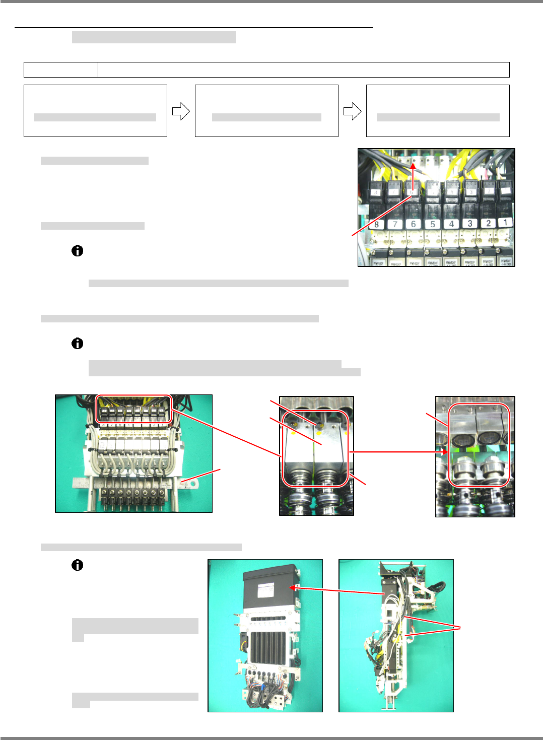
2. Disconnect the connector of the valve. (Fig. 1)
バルブのコネクタを抜きます。
(Fig. 1)
拔下阀的连接器。
(Fig. 1)
When disconnecting the connectors, be
careful not to break the wires. Do not pull the
cables.
コネクタを抜く時は、配線を切らないように注意してください。ケーブルを引っ張らないこと。
拔连接器时,请注意不要切断配线。不可拉拽电缆。
3. Insert a scale into the housing and separate the Z-axis linear motor from the ball spline. (Fig. 2)
ハウジング部にスケール等を挟み、
Z
軸リニアモータとボールスプラインの連結を分離します。
(Fig. 2)
在壳的部位夹入直尺等,使
Z
轴线性电机与滚珠花键的连结分离开来。
(Fig. 2)
The shafts of the Z-axis linear motor and ball spline are coupled with the plate.
Unseparated fitting part is can cause the shaft of the linear motor or ball spline to bend.
Z
軸リニアモータのシャフトとボールスプラインのシャフトはプレートで連結されています。
かみ合い部分を分離しないとリニアモータかボールスプラインのシャフトを曲げる原因になります。
Z
轴线性电机的轴与滚珠花键的轴是用板连结的。
如果不将咬合的部分分离,则可能使线性电机或者滚珠花键的轴弯曲。
4. Detach the Z-axis linear motor from the plate of the head unit. (Fig. 3)
ヘッドユニットのプレートから
Z
軸リニアモータを取り外します。
(Fig. 3)
从贴装头装置的板上将
Z
轴线性电机拆下。
(Fig. 3)
①
The Z-axis linear motor is
located by the positioning
pin (2-
5x10) and secured
with the bolt (4-M5x16).
Z
軸リニアモータは、規正ピン
(2-
5
10)
で位置
決めされ、ボルト
(4-M5 x 16)
で固定されていま
す。
Z
轴线性电机是由定位销
(2-
5
10)
定位、并用螺
栓
(4-M5 x 16)
固定的。
②
Cut the cable ties that
bundle the wires and tubes
as appropriate.
必要に応じて配線、配管の結束バンドを切断し
ます。
必要时可以切断配线、配管的绑扎带。
Fig. 3
4-M5 x 16
Fig. 2
Must be
separated
Scale
Fitting part
Plate
M2 x 6
NPM-D3
Service Manual
5.5 Light Weight 16-Nozzle Head
EJM6D3-MB-05SM-00(
編集中
).DOC Page 5-65
Fig. 4
Make sure to fall
smoothly.
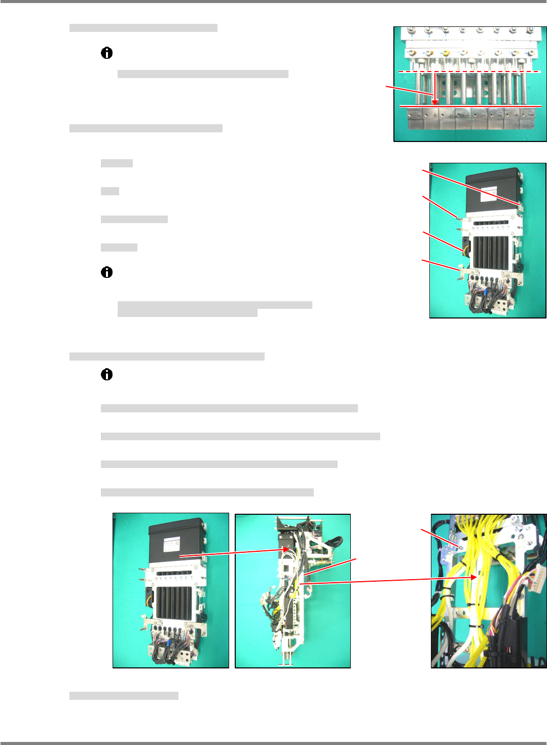
5. Check the new Z-axis linear motor for proper sliding. (Fig. 4)
新しい
Z
軸リニアモータの摺動を確認します。
(Fig. 4)
确认新的
Z
轴线性电机的滑动情况。
(Fig. 4)
Make sure that all slide shafts slide
smoothly by their own weight.
すべてのスライドシャフトが、自重でスムーズに下降すること。
所有的滑动轴应能以自重滑顺地下降。
6. Fit the attached parts to the new linear motor.
(Fig. 5)
新しいリニアモータに付属部品を付け替えます。
(Fig. 5)
向新的线性电机换装上附属部件。
(Fig. 5)
①
Fan motor
FAN
モータ
风扇电机
②
Post
ポスト
柱
③
Bracket for securing wires
配線固定用のブラケット
固定配线的托架
④
Tie mount
タイマウント
带固定螺丝的绑扎带
The bolt and washer of the linear motor are made of
stainless steel.
Do not use the products made from iron.
リニアモータ部のボルト、ワッシャはステンレス製を使用しています。
鉄製のボルト、ワッシャは使用しないでください。
线性电机部分的螺栓、垫圈应使用不锈钢制的。
请不要使用铁制的螺栓、垫圈。
7. Attach the Z-axis linear motor to the plate of the head unit. (Fig. 6)
Z
軸リニアモータをヘッドユニットのプレートに取り付けます。
(Fig. 6)
将
Z
轴线性电机装到贴装头装置的板上。
(Fig. 6)
①
The Z-axis linear motor is located by the positioning pin (2-
5x10) and secured with the bolt
(4-M5x16).
Z
軸リニアモータは、規正ピン
(2-
5
10)
で位置決めされ、ボルト
(4-M5 x 16)
で固定されます。
Z
轴线性电机是由定位销
(2-
5
10)
定位、并用螺栓
(4-M5 x 16)
固定的。
②
Make sure that the shafts of the Z-axis linear motor and ball spline will not interfere with each other.
Z
軸リニアモータのシャフトとボールスプラインのシャフトを干渉させないように注意してください。
请注意不要让
Z
轴线性电机的轴与滚珠花键的轴相干涉。
③
Couple the shafts of the Z-axis linear motor and ball spline with the plate.
Z
軸リニアモータのシャフトとボールスプラインのシャフトをプレートで連結します。
用板连结
Z
轴线性电机的轴与滚珠花键的轴。
④
Use new cable ties to secure the wires and tubes where the old cable ties were cut.
切断した結束バンドの個所は、新しい結束バンドで配線、配管を固定します。
对切断了绑扎带的部位,用新的绑扎带将配线、配管固定住。
8. Reattach the Z-axis control board.
Z
軸コントロール基板を取り付けます。
装上
Z
轴控制基板。
‘5.5.1 Z-axis Control Board Detaching / Attaching’
Bracket
Fan moto
r
Tie mount
Pos
t
Fig. 5
4-M5 x 16
2-
5 x 10
Fig. 6