NPM-D3维修手册.pdf - 第185页
NPM-D3 Service Manual 5.5 Light Weight 16-Nozzle Hea d EJM6D3-MB-05SM-00( 編集中 ).DOC Page 5-57 5.5.5 Ball Spline Replacement ボールスプラインの交換 滚珠花键的更换 Unit No. N610096433AA 5.5.3 Unit Detaching / Attaching ユニットの取り外し / 取り付け …
NPM-D3
Service Manual
5.5 Light Weight 16-Nozzle Head
Page 5-56 EJM6D3-MB-05SM-00(
編集中
).DOC
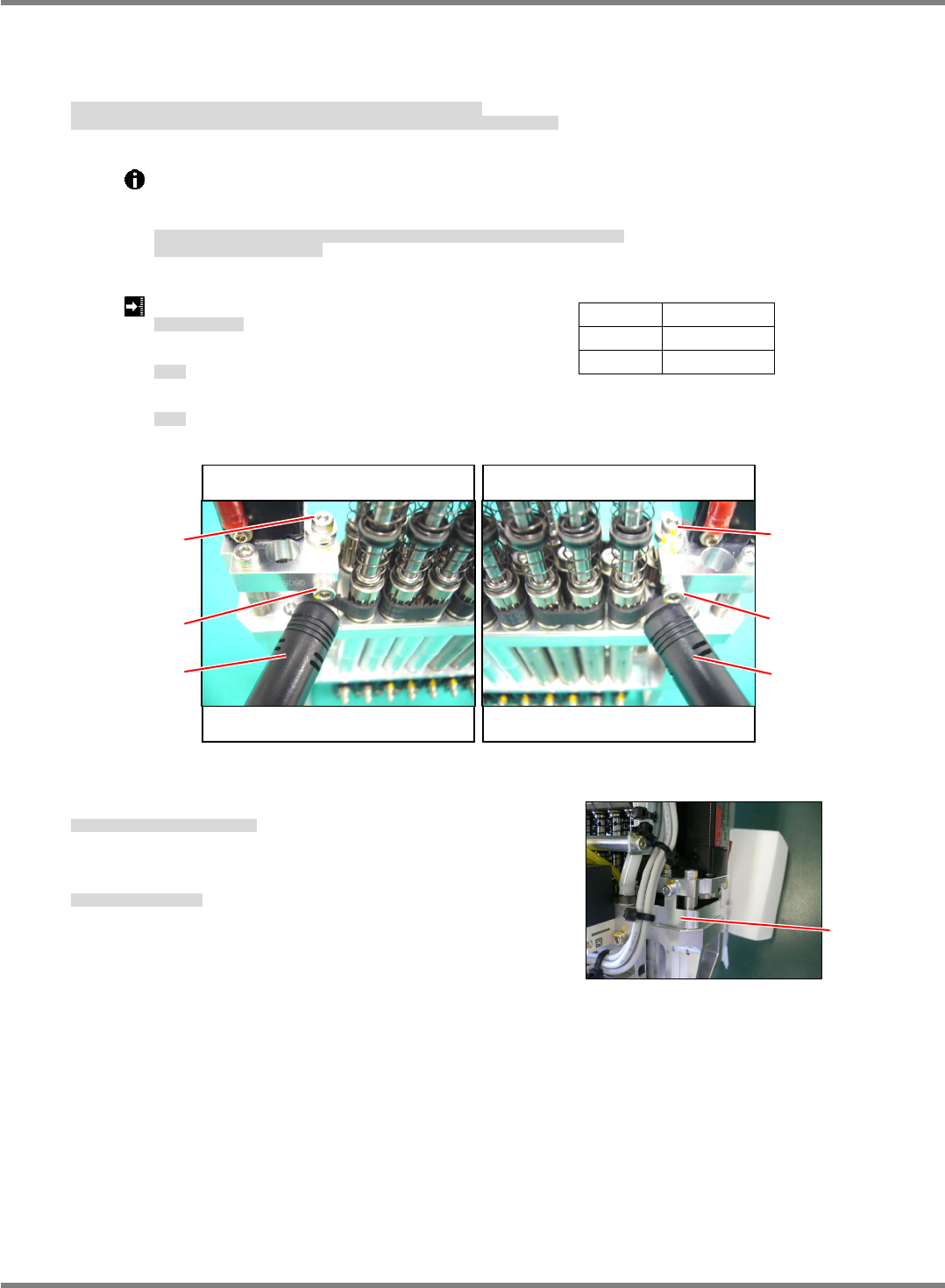
8. Measure the tension at six points for a single turn of the belt and obtain the average, maximum and
minimum values.
Adjust the tension and tighten the bolt (M3x10) of the tension roller at the position of the reference value.
(Fig. 3)
ベルト
1
回転中の
6
か所でテンションを測定し、平均値、最大値、最小値を求めます。
テンションを調整し、基準値となる位置でテンションローラ固定のボルト
(M3 x 10)
を締めます。
(Fig. 3)
测量皮带一周中的
6
处的张力,求得平均值、最大值、最小值。
调整张力,在能达到标准值的位置处拧紧张力滚轮的固定螺栓
(M3 x 10)
。
(Fig. 3)
Inserting the bolt (M3x6) into the block of the tension roller makes the tension adjustment
easy.
Remove the bolt after making the adjustment.
テンションローラのブロックにボルト
(M3 x 6)
を挿入すると、テンションの調整が容易に行えます。
調整後はボルトを外してください。
如在张力滚轮的块中插入螺栓
(M3 x 6)
,张力的调整就比较容易进行。
调整后请拆下螺栓。
belt tension: 14
2 N (Average value)
ベルトテンション
皮带张力
Maximum value: 19 N
最大値
最大值
Minimum value: 9 N
最小値
最小值
9. Attach the
belt cover. (Fig. 4)
ベルトカバーを取り付けます。
(Fig. 4)
装上
皮带的盖。
(Fig. 4)
10. Attach the
unit.
ユニットを取り付けます。
安装
装置。
‘5.5.3
Unit Detaching / Attaching’.
Span 31 mm
Width 6 mm
Mass
1.3
g
/m
Fig. 3
Nozzles No. 9 to 12 Nozzles No. 13 to 16
M3
10
Sonic
tension-mete
r
Sonic
tension-meter
M3
10
Nozzles No. 1 to 4 Nozzles No. 5 to 8
M3
6
M3
6
Fig. 4
Cover
NPM-D3
Service Manual
5.5 Light Weight 16-Nozzle Head
EJM6D3-MB-05SM-00(
編集中
).DOC Page 5-57
5.5.5 Ball Spline Replacement
ボールスプラインの交換
滚珠花键的更换
Unit No.
N610096433AA
5.5.3
Unit Detaching / Attaching
ユニットの取り外し
/
取り付け
装置的拆卸
/
安装
5.5.5 Ball Spline Replacement
ボールスプラインの交換
滚珠花键的更换
5.5.3
Unit Detaching / Attaching
ユニットの取り外し
/
取り付け
装置的拆卸
/
安装
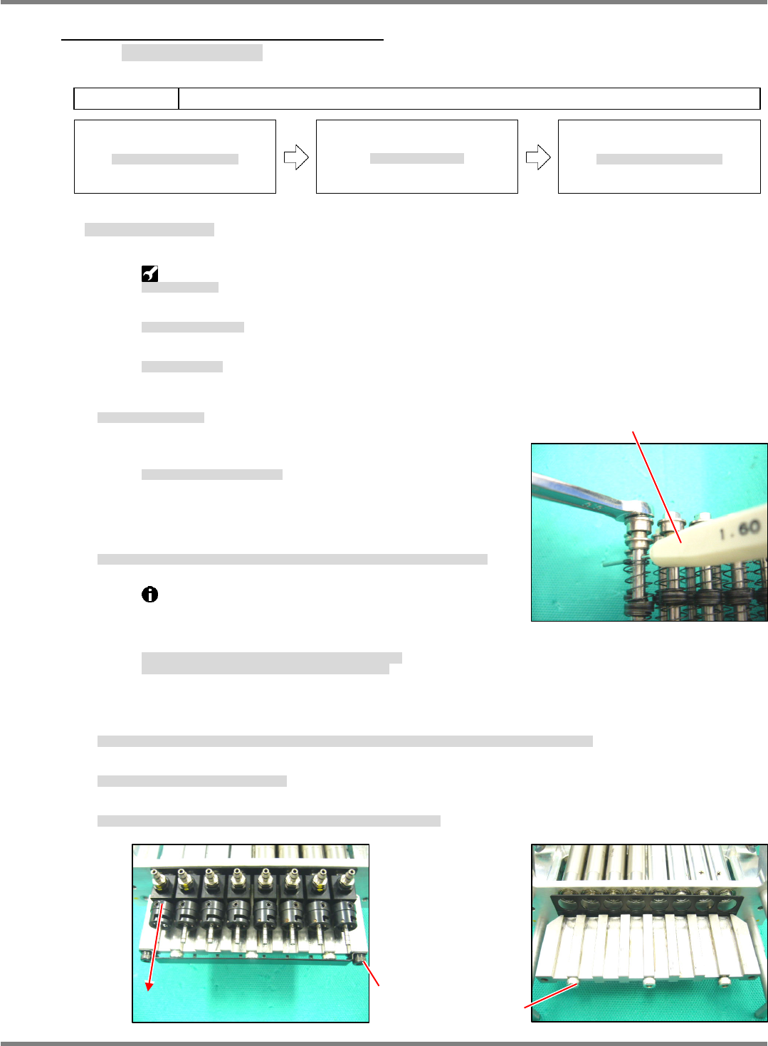
Ball Spline Detaching
ボールスプラインの取り外し
滚珠花键的拆卸
Nut tightening jig:
N610097619AA
ナット締め付け治具
螺母拧紧治具
Nut wrench (for 16-nozzle):
N210048936AD
N510025891AA
KXF06PMAA00
ナットレンチ
(16
ノズル用
)
螺母扳手(用于
16
吸嘴的)
Quenched pin (
1.6 mm)
焼入れピン
(
1.6 mm)
淬火的销
(
1.6 mm)
25.
1. Detach the
unit.
ユニットを取り外します。
拆下
装置。
‘5.5.3
Unit Detaching / Attaching’
Detach the
-axis motor and belt.
軸モータとベルトを取り外します。
拆下
轴电机和皮带。
‘5.5.4
-axis Motor / Belt Replacement’
2. Insert the quenched pin (
1.6 mm) into the hole of the shaft to stop
turning it, and loosen and remove the nut. (Fig. 1)
シャフトの穴に焼入れピン
(
1.6 mm)
ピンを挿入して回り止めとし、ナットを緩めて外します。
(Fig. 1)
将淬火销
(
1.6 mm)
插入轴的孔内进行止转,然后松开并拆下螺母。
(Fig. 1)
Be sure to use the quenched pin (
1.6 mm) to stop
turning the shafts.
Using the Allen wrench generates impressions, causing
improper sliding action.
シャフトの周り止めには必ず焼入れピン
(
1.6 mm)
を使用すること。
六角レンチなどは圧痕ができ、スライド不良の原因になります。
要进行轴的止转时必须使用淬火的销
(
1.6 mm)
。
如用六角扳手的话会出现压痕,造成滑动不良。
3. Remove the quenched pin carefully not to let the spring fly off, and then the bearing, collar, spring, guide
and washer.
スプリングが飛び出さないように注意して焼入れピンを抜き、ベアリング、カラー、スプリング、ガイド、ワッシャを抜きます。
在注意不要使弹簧跳掉的同时拔出淬火销,然后拔出轴承、轴环、弹簧、导向环、垫圈。
4. Detach the cover and remove the shaft. (Fig. 2)
カバーを取り外し、シャフトを抜きます。
(Fig. 2)
卸下盖,拔下轴。
(Fig. 2)
5. Detach the plates for guiding the housing and for holding the bearing. (Fig. 3)
ハウジングをガイドしているプレートとベアリング押さえのプレートを外します。
(Fig. 3)
卸下导引壳的板和压住轴承的板。
(Fig. 3)
Fig. 1
Quenched pin
Fig. 3
3-M3
40
Fig. 2
2-M3
6
NPM-D3
Service Manual
5.5 Light Weight 16-Nozzle Head
Page 5-58 EJM6D3-MB-05SM-00(
編集中
).DOC
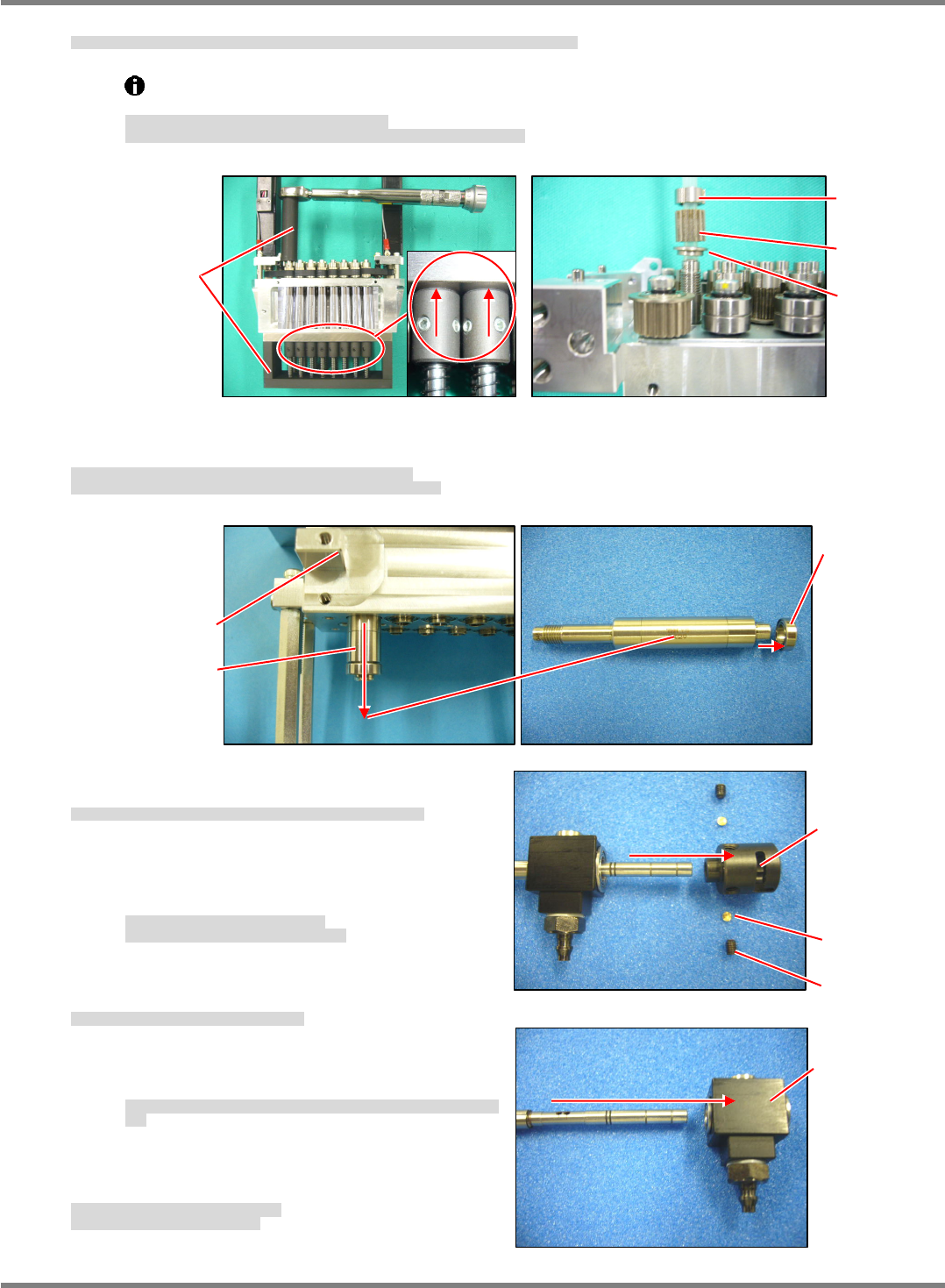
6. Place the bracket to the nut tightening jig and loosen the nut, and remove the nut, pulley and collar. (Fig. 4)
ブラケットをナット締め付け治具にセットしてナットを緩め、ナット、プーリ、カラーを外します。
(Fig. 4)
将托架放在螺母拧紧治具上,松开螺母,然后卸下螺母、皮带轮、轴环。
(Fig. 4)
Make sure that the pins of the nut tightening jig are completely raised.
Incomplete rising of the pins can deform the holes in the nut of the ball spline.
ナット締め付け治具のピンが完全に上昇していること。
上昇が不完全な場合は、ボールスプラインのナットの穴が変形する場合があります。
螺母拧紧治具的销要完全上升。
如果上升不完全,则滚珠花键的螺母的孔可能会变形。
7. Remove the nut of the ball spline from the bracket of the
unit.
Take care not to deform or damage the bearing when removing from the nut. (Fig. 5)
ユニットのブラケットからボールスプラインのナットを抜き取ります。
ナットからベアリングを変形や破損させないように注意して抜きます。
(Fig. 5)
从
装置的托架上拔下滚珠花键的螺母。
从螺母上拔下轴承,同时注意不要有变形和损坏。
(Fig. 5)
8. Loosen the lock screw (2-M2.53) and remove the
holder from the shaft. (Fig. 6)
止めねじ
(2-M2.5
3)
を緩め、シャフトからホルダを抜き取ります。
(Fig. 6)
松开固定螺丝
(2-M2.5
3)
,从轴上拔下支架。
(Fig. 6)
=NOTE=
Pieces are incorporated at the end of the lock
screw.
Be careful not to lose them.
止めねじの先端にピースが入っています。
ピースを紛失しないように注意してください。
在固定螺丝的端部有一个小块。
请注意不要使小块丢失。
9. Remove the housing from the shaft. (Fig. 7)
シャフトからハウジングを抜き取ります。
(Fig. 7)
从轴上拔下壳。
(Fig. 7)
=NOTE=
Be careful not to damage the packing in the
housing.
ハウジング内部のパッキングを傷つけないように、注意してハウジングを抜きま
す。
拔下壳时,请注意不要弄伤壳内部的密封圈。
10. This completes the disassembly of the ball spline.
Replace the ball spline with a new one.
以上でボールスプラインの分解が完了です。
新しいボールスプラインに交換します。
以上,滚珠花键的分解就结束了。
然后换装上新的滚珠花键。
Fig. 6
Holder
Piece
M2.5
3
Fig. 7
Housing
Fig. 5
Nu
t
Bracke
t
Bearing
Fig. 4
Nut tightening jig
Nut
Pulley
Collar