NPM-D3维修手册.pdf - 第153页
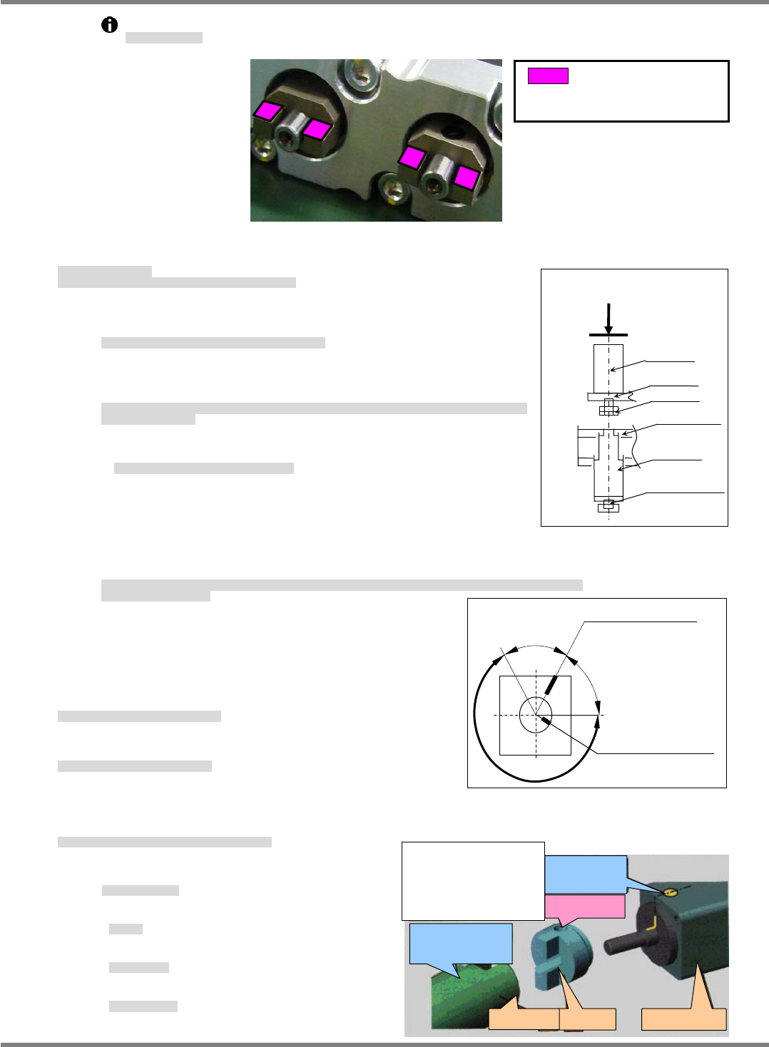
NPM-D3 Service Manual 5.3 8-nozzle Head EJM6D3-MB-05SM-00( 編集中 ).DOC Page 5-25 Fig. 2 Guide Set screw Bearing 5.3.2 Ball Spline Replacement ボールスプライン交換 滚珠花键的交换 Unit No. N610067507AA 5.1.1 Head Unit Detaching an d Attachin…
NPM-D3
Service Manual
5.3 8-nozzle Head
Page 5-24 EJM6D3-MB-05SM-00(
編集中
).DOC
Ball screw
Motor
Plate
Joint
Bracket
Shaft
A
Fig. 4
Grease connections.
連結部にグリス塗布
在连接部涂敷润滑脂
5. Attach the motor.
How to assemble the Z-axis motor (How to assemble the Z-axis motor and ball screw)
モータを取り付けます。
Z 軸モータの組付け方 (Z 軸モータとボールネジの組付け方法)
安装电机。
Z 电机的组装方法 (Z 电机和滚珠丝杠的组装方法)
①
Slide the ball screw to the upper limit stopper position. (Fig. 4)
ボールネジを上限ストッパー位置まで移動させる。(Fig. 4)
将滚珠丝杠移动到上限止动器位置。(Fig. 4)
②
Turn the motor shaft so that the grooves on the ball screw align with
the projections of the joint, and couple together.
ボールネジのマイナスドライバ溝とジョイントのマイナスドライバ面がほぼ同方向になる様にモータのシャフ
トを回転させ組付ける。
为了使滚珠丝杠的一字型螺丝刀沟槽和接头的一字型螺丝刀面几乎成为同一个方向,转动电机轴,并组装。
Hold the ball screw at the upper limit stopper.
ボールネジは上限ストッパー位置を保持する事
滚珠丝杠应保持上限止动器的位置
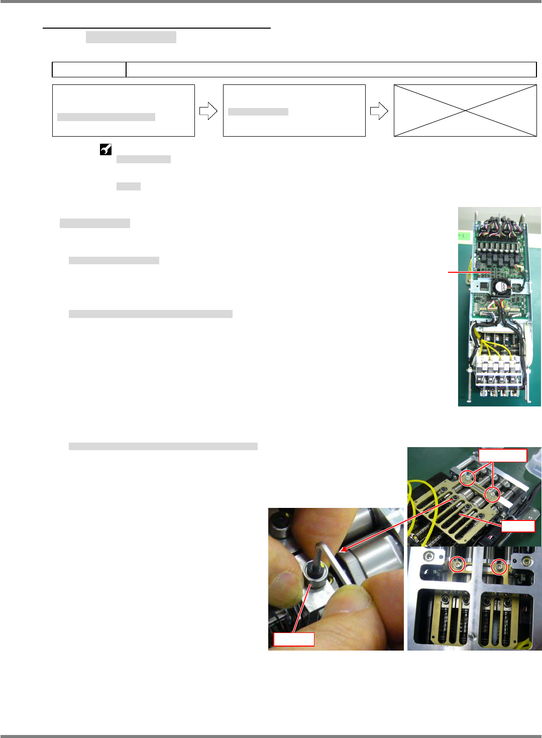
③
The C channel output position of the motor shaft at this time is on
the top of the motor. Do not position the C channel output within 60
on either side of the C channel output position on the top of the
motor.
(Position with the 240
area of Fig. 5.)
このとき、モータシャフトの C チャンネル出力位置は、モータ上部の C チャンネル出力位置前後 60には、配置しないこと。
(Fig. 5 の 240範囲内に配置)
此时,电机轴部的 C 频道输出位置不可配置于电机上部的 C 频道输出位置的前后 60 以内。
(应在 Fig. 5 中的 240 范围内配置)
6. Wire the head unit Z-axis motor.
ヘッドユニット Z モータの配線をします。
连接头装置 Z 电机的配线。
7. Attach the head unit cover.
ヘッドユニットカバーを取り付けます。
安装头装置的盖。
‘5.1.1 Head Unit Detaching and Attaching’.
8. After attaching the head unit, perform the following procedures.
ヘッドユニット取り付け後は以下の作業を実施します。
安装好头装置以后,进行以下作业。
Calibration
キャリブレーション
校准
• Z plane calibration
面補正
Z
面补正
Z
• Part recognition camera
部品認識カメラ
元件识别照相机
• Jig station
ジグステーション
治具站
:Greasing surface
Grease also on the rear
surface.
Grease: Panasonic LCG100
C channel output
position on the top of
the motor
60
60
C channel output
position of the motor
shaft
NG
NG
0K
Fig. 5
Screw hole
Motor origin
marking
Joint
Z-
a
xi
s
m
o
t
or
Shaft
When engaging the joint
with the shaft, the marking
on the motor must be more
than 60
away from the
screw hole of the shaft.
Raise it almost to
maximum.
NPM-D3
Service Manual
5.3 8-nozzle Head
EJM6D3-MB-05SM-00(
編集中
).DOC Page 5-25
Fig. 2
Guide
Set screw
Bearing
5.3.2 Ball Spline Replacement
ボールスプライン交換
滚珠花键的交换
Unit No.
N610067507AA
5.1.1 Head Unit Detaching and
Attaching
ヘッドユニット取り外し
/
取り付け
头装置的拆卸和安装
5.3.2 Ball Spline Replacement
ボールスプライン交換
滚珠花键的交换
Push-pull gauge
プッシュプルゲージ
推拉规
Scale
スケール
标尺
Ball Spline Replacement
ボールスプライン交換
滚珠花键的交换
11.
1. Ball Spline Replacement
ヘッドユニットを取り外します。
卸下头装置。
‘5.1.1 Head Unit Detaching and Attaching’
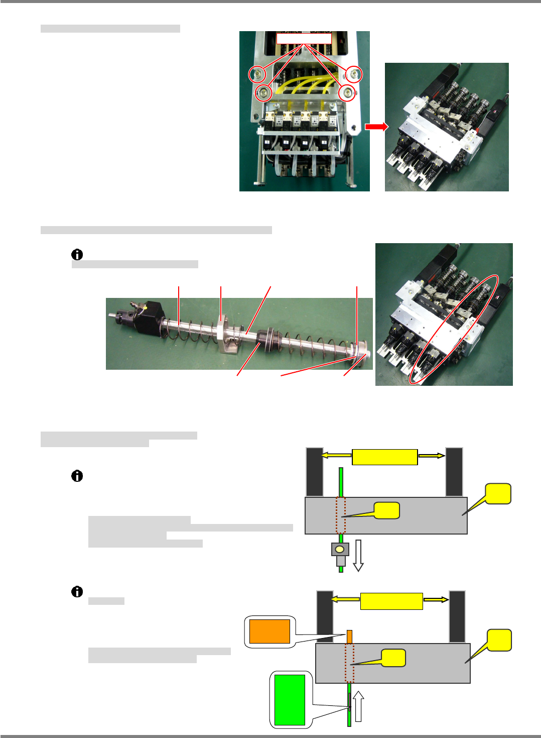
2. Detach the head unit cover and the front board. (Fig. 1)
ヘッドユニツトカバーを外し、正面基板を外します。(Fig. 1)
拆下头装置盖后,卸下正面基板。(Fig. 1)
3. Detach the coupling between the ball spline and Z-axis ball screw. (Fig. 2)
ボールスプラインの Z 軸ボールネジの連結部を取り外します。(Fig. 2)
卸下滚珠花键的 Z 轴滚珠丝杠的连接部。(Fig. 2)
Board
Fig. 1
NPM-D3
Service Manual
5.3 8-nozzle Head
Page 5-26 EJM6D3-MB-05SM-00(
編集中
).DOC
moto
r
A
B
0026
0026
4. Detach the
drive unit from the head unit. (Fig. 3)
ヘッドユニット部から
駆動部を外します。(Fig. 3)
从头装置部卸下
驱动部。(Fig. 3)
5. Remove the bolt from the ball spline and detach the collar, bearing, etc. (Fig. 4)
ボールスプラインのボルトを外し、カラー / ベアリングなどを取り外します。(Fig. 4)
卸下滚珠花键的螺栓后,卸下轴环 / 轴承等。(Fig. 4)
Be careful as the spring may fly when tension is released.
スプリングが飛び出るので注意してください。
请注意弹簧的弹出。
6. Pull the ball spline out from the bearing case.
Insert a new ball spline.
ベアリングケースからボールスプラインを引き抜きます。
新しいボールスプラインと交換します。
从轴承盒里拔出滚珠花键。
换上新的滚珠花键。
Do not grease the shaft of the ball spline.
The shaft of the ball spline is automatically
lubricated, therefore greasing is unnecessary.
For that reason as well, do not wipe off grease.
ボールスプラインへのグリス塗布禁止
ボールスプラインのシャフト部分のグリスに関しては、自動給脂のため、グ
リスの塗布は不要とします。
そのため、グリスふき取りは禁止します。
禁止在滚珠花键涂敷润滑脂
关于滚珠花键的轴部分的润滑脂,被自动供给,
因此不需要涂敷润滑脂。
因此,禁止擦拭润滑脂。
Shaft insertion
シャフト挿入
插入轴
Align the bearing case (B) and
ball spline (A) as shown at right
and insert the shaft.
ベアリングケース
(B)
とボールスプライン
(A)
の番
号の方向を合わせて挿入してください。
请确保轴承盒
(B)
和滚珠花键
(A)
的编号方向一致,将
轴插入。
A
: Housing
B: Bearing case
motor
A
B
Set scre
w
Fig. 3
Fig. 4
Spring Ball splineHolder Collar
BearingGuide Washer bolt