NPM-D3维修手册.pdf - 第241页
NPM-D3 SERVICE MANUAL 6.3 XY Drivers EJM6D3-MB-06SM-00( 編集中 ).DOC Page 6-21 6.3 XY Drivers XY ドライバ XY 驱动器 6.3.1 Driver Setting ドライバ設定 驱动器设定 Description 表示説明 显示说明 Node Address Setting (MAC-ID) ノードアドレス (MAC-ID) の設定 节点地…
NPM-D3
SERVICE MANUAL
6.2 P9 Controller
Page 6-20 EJM6D3-MB-06SM-00(
編集中
).DOC
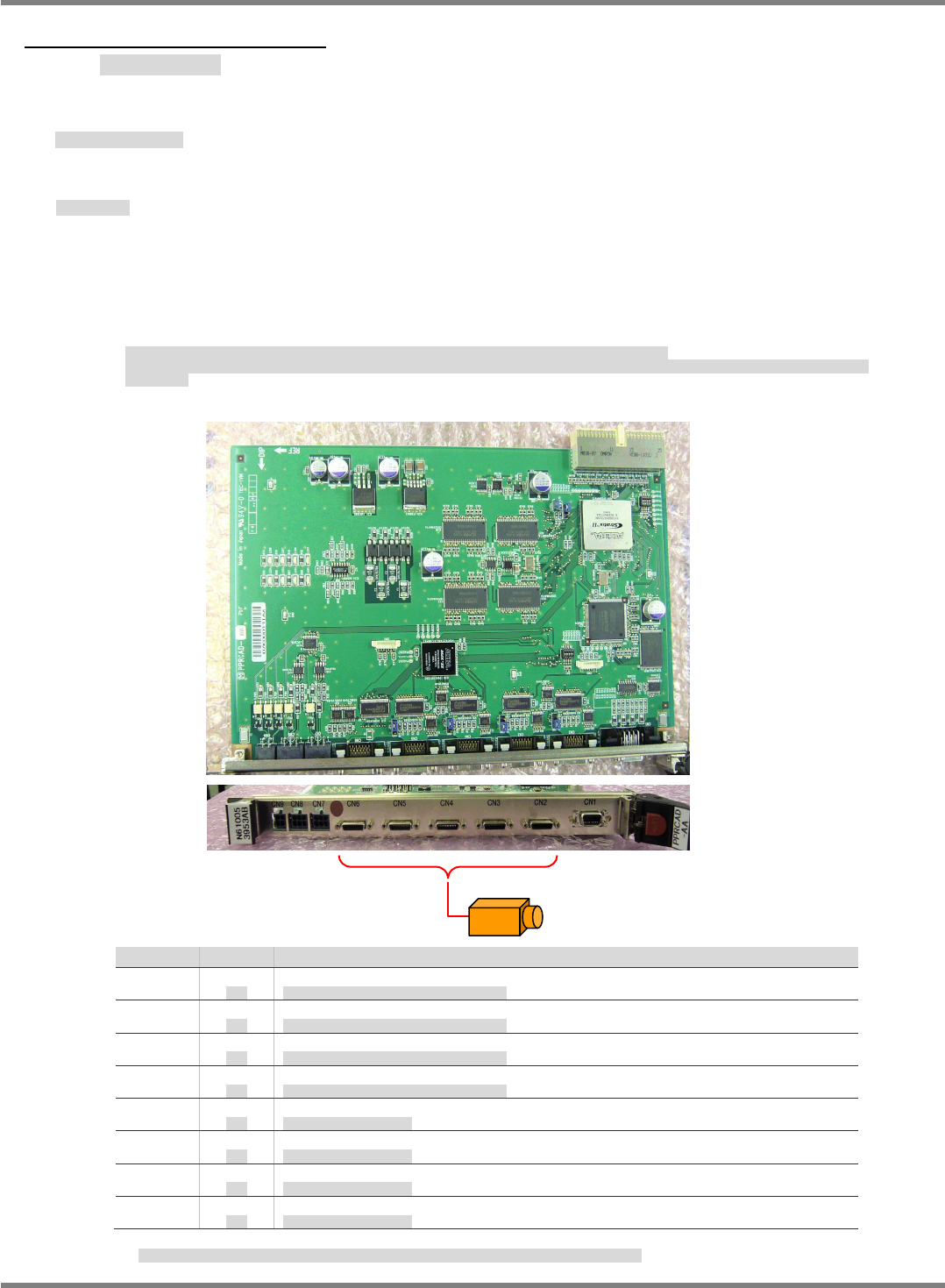
6.2.4 Camera I/F Board
カメラ I/F ボード
照相机 I/F 板
Name: Camera I/F board (Model: PRCAD-AA Part No.:
N610053953AC
)
名称
:
カメラ
I/F
ボード
名称
:
照相机
I/F
板
Basic Specifications
基本スペック
基本规格
This board interfaces with the recognition modules such as cameras and line sensors. It has no
CPU.
As the recognition monitor function, the board transfers the image data captured by cameras to
the CPU board (NBC
JC154X
D5) via the internal bus. The data is superimposed on the control
panel display by the CPU board.
カメラ、ラインセンサなどの認識モジュールのインターフェイス機能を有するボードで、内部に
CPU
を持たない。
認識モニタ機能は、カメラから取り込まれた画像データを内部バスで
CPU
ボード
(NBC
JC154X
D5)
に転送し、
CPU
ボードから操作盤表示を行う際、イン
ポーズする。
本板备有照相机、线性传感器等的识别模块的界面功能,内部没有
CPU
。
识别监视功能是,用内部总线,从照相机获取的画像数据传送给
CPU
板
(NBC
JC154X
D5)
,并从
CPU
板进行操作盘的显示时,将画面叠加显示。
No. OK 内容
LED1
Unlit
消灯
Checking the CH2 Camera cable disconnecting
CH2
に接続するカメラケーブルの断線チェック
LED2
Unlit
消灯
Checking the CH3 Camera cable disconnecting
CH3
に接続するカメラケーブルの断線チェック
LED3
Unlit
消灯
Checking the CH4 Camera cable disconnecting
CH4
に接続するカメラケーブルの断線チェック
LED4
Unlit
消灯
Checking the CH5 Camera cable disconnecting
CH5
に接続するカメラケーブルの断線チェック
LED5
Unlit
消灯
Power supply for CH2 Camera
CH2
のカメラへの電源供給
LED6
Unlit
消灯
Power supply for CH3 Camera
CH3
のカメラへの電源供給
LED7
Unlit
消灯
Power supply for CH4 Camera
CH4
のカメラへの電源供給
LED8
Unlit
消灯
Power supply for CH5 Camera
CH5
のカメラへの電源供給
When the image is loaded, LED1-4 disconnecting is checked. And only Clock signal cable is checked.
LED1~4
の断線チェックはカメラ画像の取り込み中にのみ機能し、チェックするのはクロック線のみです。
Fixed camera / Head camera
NPM-D3
SERVICE MANUAL
6.3 XY Drivers
EJM6D3-MB-06SM-00(
編集中
).DOC Page 6-21
6.3 XY Drivers
XY ドライバ
XY 驱动器
6.3.1 Driver Setting
ドライバ設定
驱动器设定
Description
表示説明
显示说明
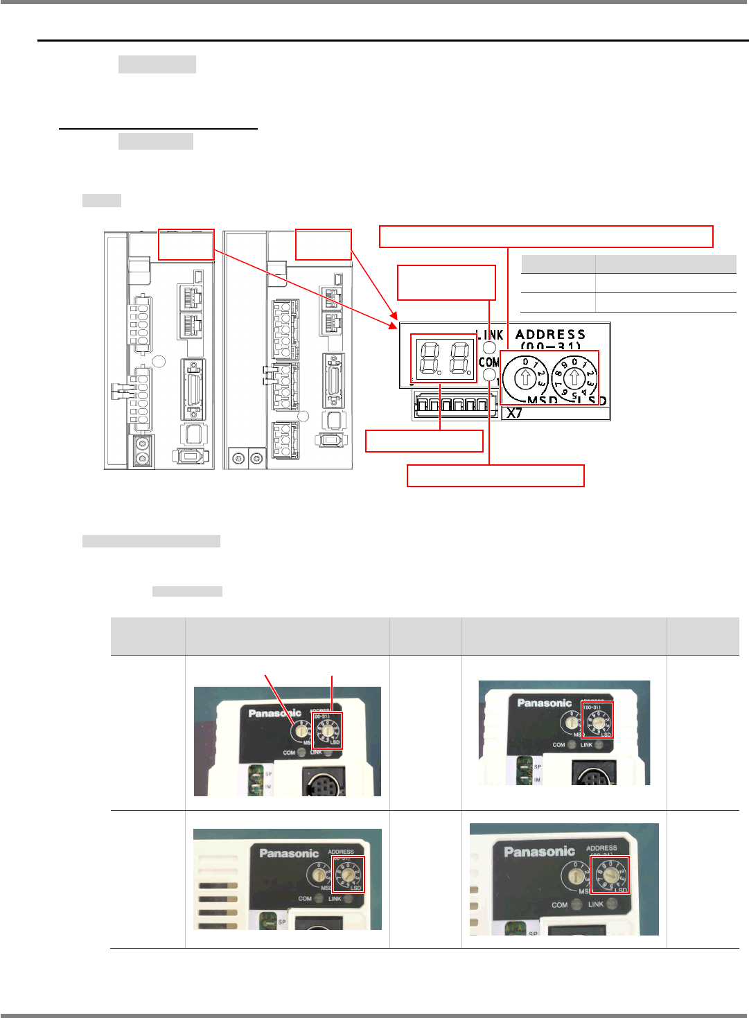
Node Address Setting (MAC-ID)
ノードアドレス(MAC-ID)の設定
节点地址 (MAC-ID) 的设定
Set MSD to 0 for all axes.
MSD は全軸とも‘0’
MSD,全轴都是 ‘0’
Front
FRONT
前
Set value
設定値
设定值
Rear
REAR
后
Set value
設定値
设定值
X-axis
X
軸
X
轴
0
2
Y-axis
Y
軸
Y
轴
1 3
MSD LSD
For X-axis
(MCDHT3520NL2)
For Y-axis
(MEDHT7364NL3)
Set value Contents
0 to 31 Node address value
Other Err.82 occurs
Rotary switch for node address (MAC-ID) setting
Network status LED (COM)
Network status
LED (LINK)
7 segment LED
NPM-D3
SERVICE MANUAL
6.3 XY Drivers
Page 6-22 EJM6D3-MB-06SM-00(
編集中
).DOC
6.3.2 7-Segment LED
7 セグメント LED の表示
7 段 LED 的显示
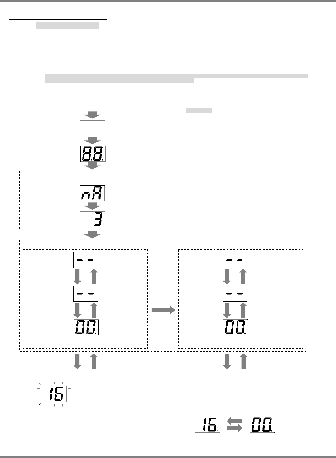
The node address set by the rotary switch is shown when power is turned ON, and then usually
“- -”(servo OFF) appears followed by “00”(Servo ON) on the LED display.
However, an alarm code is displayed when an alarm has occurred, and a warning code is shown
if a warning has occurred.
電源投入時には、ロータリースイッチで設定されたノードアドレス値を表示し、その後、通常状態(
“
--
”
サーボオフ、
“00”
サーボオン)に移行します。
ただし、アラーム発生時にはアラームコードを警告発生時には警告コードを表示します。
接通电源时,首先显示用旋转开关设定的节点地址值,然后转移到通常状态
( “
--
”
伺服
OFF
、
“00”
伺服
ON)
。
但是,警报发生时,显示警报代码,警告发生时显示警告代码。
‘Error code list’.
‘
エラーコード
’
‘
错误代码
’
。
Normal state
Main power is
ON and the
network is
established.
Servo: ON
Main power is
OFF or the
network is not
established.
Servo: OFF
Same as normal state
Main power is
ON and the
network is
established.
Servo: ON
Main power is
OFF or the
network is not
established.
Servo: OFF
When the motor is driven
b
y
sinusoidal current, left dot is lit.
Driven by
sinusoidal
current
Alarm occurred. Alarm cleared.
Warning occurred.
Warning cleared.
<Node address (MAC-ID) display>
Rotary switch setting value (When MSD is 0 and LSD is 3.)
Alarm code
(Approx. 2 s)
<Warning display>
The LED display alternates between warning
code and normal state.
(Example: Overload)
(NOTE) An alarm code may coincide with
the normal display value.
Normal display
(Approx. 4 s)
<Alarm display>
Alarm code flashes.
(Example: Overload)
Turn the power ON.
All segments unlit
All segments are lit
(Approx. 600 ms)
[n A] (Node Address)
(Approx. 600 ms)