NPM-D3维修手册.pdf - 第174页
NPM-D3 Service Manual 5.5 Light Weight 16-Nozzle Hea d Page 5-46 EJM6D3-MB-05SM-00( 編集中 ).DOC Fig. 1 Top covers (x 2) Front cover (x 1) 5.5 Light Weight 16-Nozzle Head 軽量 16 ノズルヘッド 軽量 16 吸嘴头 5.5.1 Z θ -axis Control Board…
NPM-D3
Service Manual
5.4 2-nozzle Head
EJM6D3-MB-05SM-00(
編集中
).DOC Page 5-45
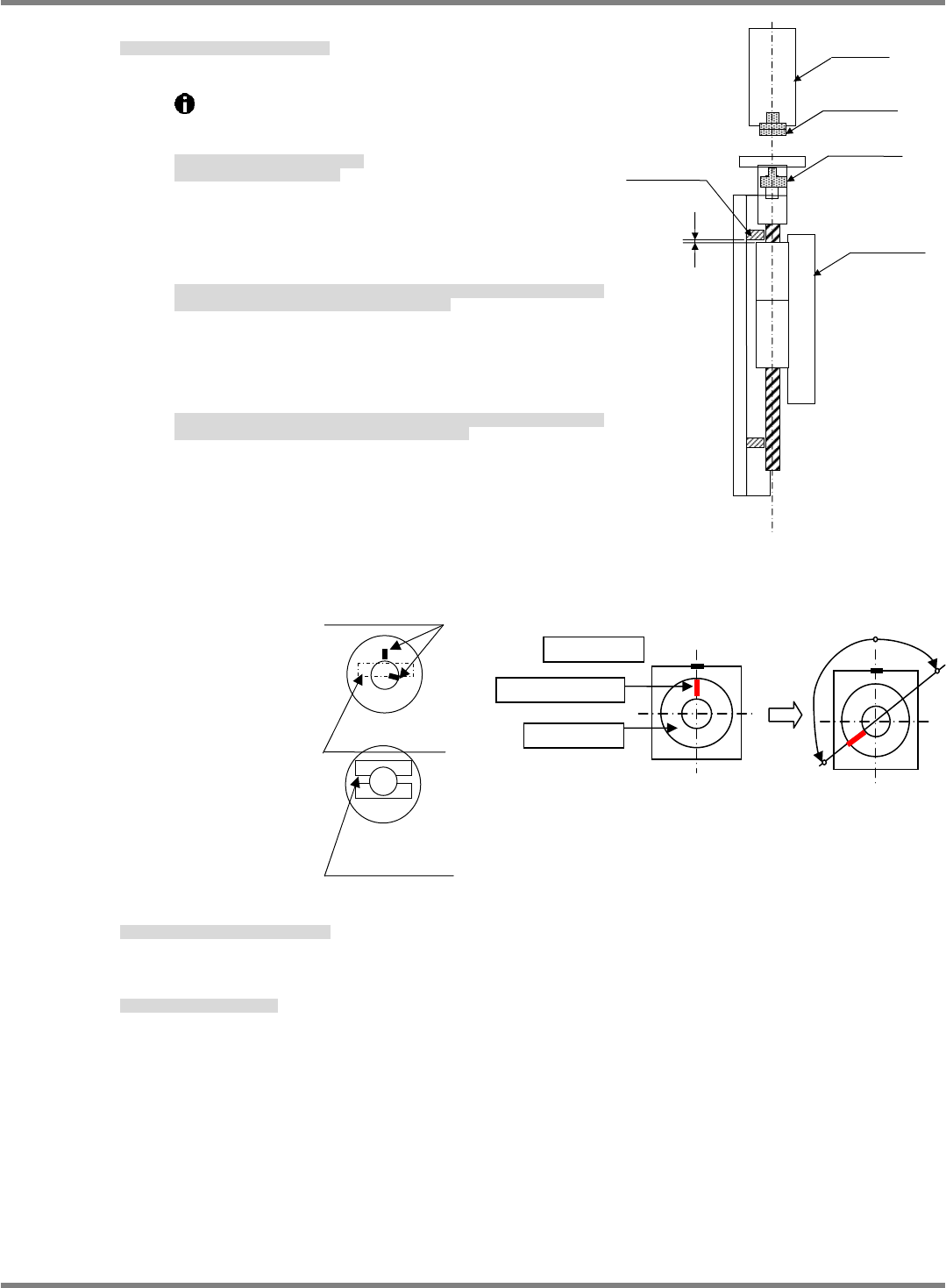
7. Assemble the Z-axis motor and tighten bolts.
Z モータを取り付けて、ボルトを締めます。
组装 Z 电机 / 拧紧螺栓。
①
Move the ball screw to the origin position.
(Upper limit stopper -2 mm)
ボールネジを原点位置まで移動します。
(上限ストッパーから-2 mm が原点)
将滚珠丝杠移动到原点位置。
(上限止动器在-2 mm 的位置为原点)
②
Set the motor and KR unit so that their slotted faces are
similarly oriented. The motor and shaft origin marks
should be separated by 90
or more at this time.
モータと KR ユニットのマイナスドライバ面がほぼ同方向になるように向けます。このとき、
モータの原点マーク同士が、約 90 以上離れていること。
使电机和 KR 装置的一字型螺丝刀面几乎向同一个方面。此时,电机的原点标记应互相分开大
约 90以上。
③
If the marks are right at 90
apart and you are unsure
whether to move the marks to the left or right, turn the
shaft mark clockwise to the mark on the motor.
丁度 90くらいで左右どちらにマークを持っていくか迷うときは、モータ本体の原点マーク
に対してシャフトのマークが時計回り側になるようにします。
在刚 90的位置上犹豫将标记移动到左右的哪一方时,对于电机主体的原点标记,使轴的标记
位于时针方向的一侧。
8. Connect connectors and attach the cover.
コネクタを差込み、カバーを取り付けます。
插入连接器后,安装盖。
9. Attach the head unit.
ヘッドユニットを取り付けます。
安装头装置。
‘Head Unit Replacement Procedure’.
Fig. 8
Joint
Joint
Z-axis motor
KR unit
2 mm
Upper limit
stopper
Origin
Slotted face of joint
Slotted face of joint
Motor origin mark
When viewed from top
○
○
Hollow setscrew
Joint
Marking
×
NPM-D3
Service Manual
5.5 Light Weight 16-Nozzle Head
Page 5-46 EJM6D3-MB-05SM-00(
編集中
).DOC
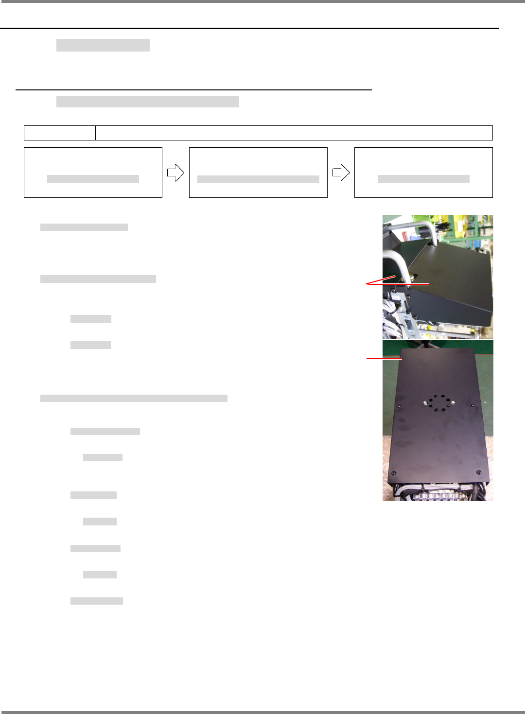
Fig. 1
Top covers (x 2)
Front cover (x 1)
5.5 Light Weight 16-Nozzle Head
軽量 16 ノズルヘッド
軽量 16 吸嘴头
5.5.1 Z
θ
-axis Control Board Detaching / Attaching
Zθ軸コントロール基板の取り外し / 取り付け
Zθ轴控制基板的拆卸 / 安装
Unit No.
N61xxxxxxxAA
5.1.1 Head Unit Detaching and
Attaching
ヘッドユニット取り外し
/
取り付け
头装置的拆卸和安装
5.5.1 Z
θ
-axis Control Board
Detaching / Attaching
Z
θ軸コントロール基板の取り外し
/
取り付け
Z
θ轴控制基板的拆卸
/
安装
5.1.1 Head Unit Detaching and
Attaching
ヘッドユニット取り外し
/
取り付け
头装置的拆卸和安装
20.
1. Detach the head unit.
ヘッドユニットを取り外します。
卸下头装置。
‘5.1.1 Head Unit Detaching and Attaching’
2. Detach the covers from the top and front of the head unit. (Fig. 1)
ヘッドユニットのカバーを外します。
(Fig 1)
拆下头装置的盖。
(Fig. 1)
Top covers (x 2)
上部カバー
(x 2)
上面盖
(x 2)
Front cover (x 1)
正面カバー
(x 1)
正面盖
(x 1)
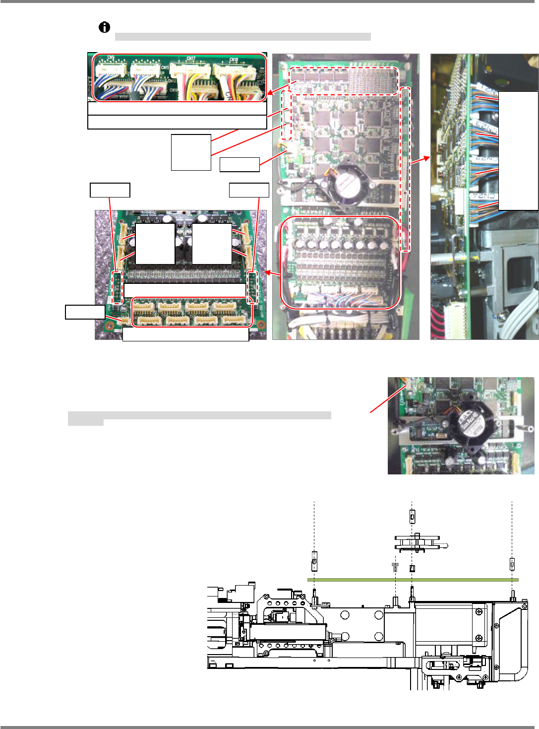
3. Disconnect the connectors of the Zθ-axis control board from the 16-nozzle
head. (Fig. 2)
16
ノズルヘッド
Z
θ軸コントロール基板のコネクタを抜きます。
(Fig 2)
拔下
16
吸嘴贴装头
Z
θ轴控制基板的连接器。
(Fig. 2)
Top rear : Z-axis encoder ( CN9 / CN10 / CN11 / CN12 )
上部裏面
: Z
軸エンコーダ
上部背面:
Z
轴编码器
: Blow valve ( CN17 / CN18 / CN19 / CN20 )
:
ブローバルブ
:
吹气阀
Lower surface : Z power ( CN1 / CN2 / CN3 / CN4 / CN5 / CN6 / CN7 /
CN8 )
下部表面
: Z
動力
下部表面
: Z
动力
: Vacuum valve ( CN13 / CN14 / CN15 / CN16 )
:
吸着バルブ
:
吸附阀
Right rear :
-axis motor ( CN33 / CN34 )
右裏面
:
軸モータ
右背面:
轴电机
: Flow sensor ( CN21 / CN22 / CN23 / CN24 )
:
流量センサ
:
流量传感器
Left rear : Fan motor ( CN27 / CN28 )
左裏面
:FAN
モータ
左背面:风扇电机
NPM-D3
Service Manual
5.5 Light Weight 16-Nozzle Head
EJM6D3-MB-05SM-00(
編集中
).DOC Page 5-47
When disconnecting the connectors, be careful not to break the wires. Do not pull the cables.
コネクタを抜く時は、配線を切らないように注意してください。ケーブルを引っ張らないこと。
拔连接器时,请注意不要切断配线。不可拉拽电缆。
4. Disconnect the connector (CN27) and detach the spacer
and remove the Zθ-axis control board from the 16-nozzle
head unit. (Fig. 3, Fig. 4)
コネクタ
(CN27)
を抜き、スペーサを外し、
16
ノズルヘッド
Z
θ軸コントロール基板を取り外します。
(Fig. 3, Fig 4)
拔出连接器
(CN27)
、取下垫片,卸下
16
吸嘴贴装头
Z
θ轴控制基板。
(Fig. 3, Fig. 4)
Fig. 2
Fig. 4
CN7 CN8 CN5 CN6
CN4 CN3 CN2 CN1
CN13
CN15
CN14
CN16
CN28
CN27
CN34 CN33
Fig. 3
CN27
CN21
CN23
CN22
CN24
CN9 CN11 CN17 CN18
CN10 CN12 CN19 CN20
CN26
CN25