NPM-D3维修手册.pdf - 第155页
NPM-D3 Service Manual 5.3 8-nozzle Head EJM6D3-MB-05SM-00( 編集中 ).DOC Page 5-27 7. Check the maximum sliding resi stance with the ball spline in a hori zontal posture. Measure resistance when dimen sion A is 38 to 78 mm. …
NPM-D3
Service Manual
5.3 8-nozzle Head
Page 5-26 EJM6D3-MB-05SM-00(
編集中
).DOC
moto
r
A
B
0026
0026
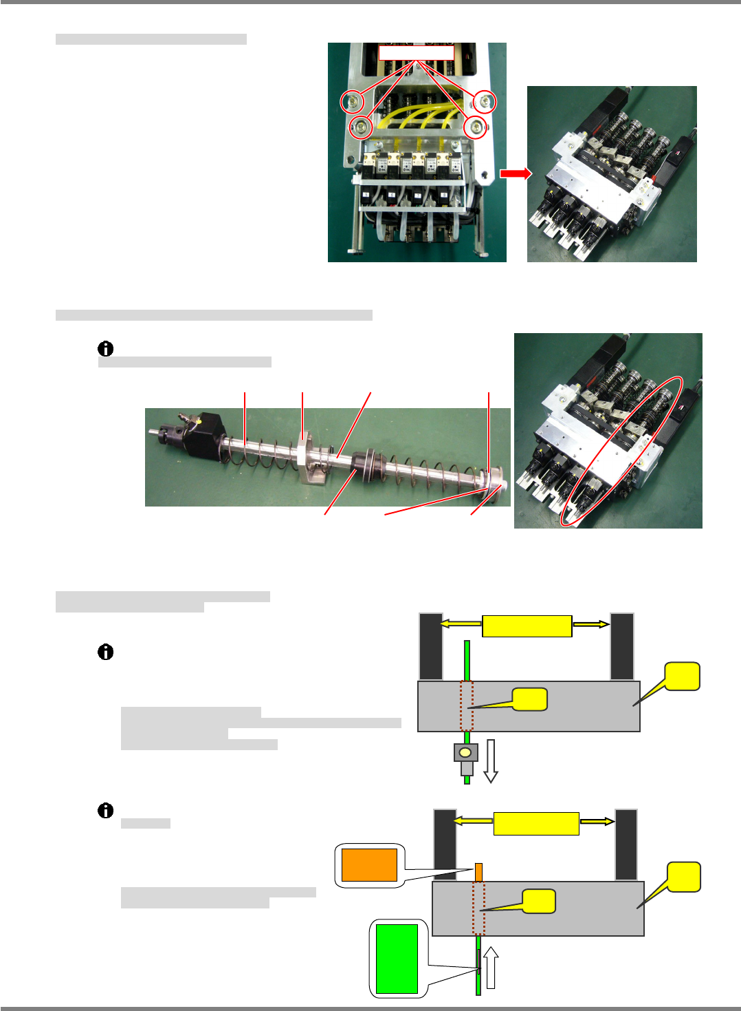
4. Detach the
drive unit from the head unit. (Fig. 3)
ヘッドユニット部から
駆動部を外します。(Fig. 3)
从头装置部卸下
驱动部。(Fig. 3)
5. Remove the bolt from the ball spline and detach the collar, bearing, etc. (Fig. 4)
ボールスプラインのボルトを外し、カラー / ベアリングなどを取り外します。(Fig. 4)
卸下滚珠花键的螺栓后,卸下轴环 / 轴承等。(Fig. 4)
Be careful as the spring may fly when tension is released.
スプリングが飛び出るので注意してください。
请注意弹簧的弹出。
6. Pull the ball spline out from the bearing case.
Insert a new ball spline.
ベアリングケースからボールスプラインを引き抜きます。
新しいボールスプラインと交換します。
从轴承盒里拔出滚珠花键。
换上新的滚珠花键。
Do not grease the shaft of the ball spline.
The shaft of the ball spline is automatically
lubricated, therefore greasing is unnecessary.
For that reason as well, do not wipe off grease.
ボールスプラインへのグリス塗布禁止
ボールスプラインのシャフト部分のグリスに関しては、自動給脂のため、グ
リスの塗布は不要とします。
そのため、グリスふき取りは禁止します。
禁止在滚珠花键涂敷润滑脂
关于滚珠花键的轴部分的润滑脂,被自动供给,
因此不需要涂敷润滑脂。
因此,禁止擦拭润滑脂。
Shaft insertion
シャフト挿入
插入轴
Align the bearing case (B) and
ball spline (A) as shown at right
and insert the shaft.
ベアリングケース
(B)
とボールスプライン
(A)
の番
号の方向を合わせて挿入してください。
请确保轴承盒
(B)
和滚珠花键
(A)
的编号方向一致,将
轴插入。
A
: Housing
B: Bearing case
motor
A
B
Set scre
w
Fig. 3
Fig. 4
Spring Ball splineHolder Collar
BearingGuide Washer bolt
NPM-D3
Service Manual
5.3 8-nozzle Head
EJM6D3-MB-05SM-00(
編集中
).DOC Page 5-27
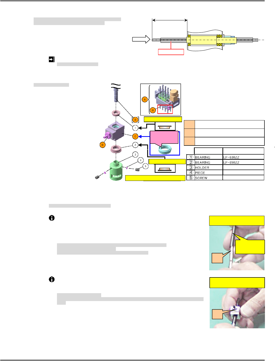
7. Check the maximum sliding resistance with the ball spline in a horizontal posture.
Measure resistance when dimension A is 38 to 78 mm.
水平状態でボールスプラインの摺動抵抗 (最大値) を確認します。
測定は A 寸法が 38~78 mm の間で行ってください。
在水平的状态下确认滚珠花键的往返移动抵抗值 (最大值) 。
A 尺寸在 38~ 78 mm 范围内进行测量。
Ball spline standalone sliding esistance requirement:
1.5 N
ボールスプライン単体摺動規格
滚珠花键单体往返移动值规格
8. Assemble the shaft.
シャフト部を組立てます。
组装轴部。
④
Insert the housing over the splined shaft.
ハウジングにボールスプラインを挿入します。
在壳里插入滚珠花键。
Use the insertion jig so as not to damage the Y packing of the spline
housing.
Thinly coat the insertion jig with grease.
This grease serves for extracting the insertion jig in later processes.
(Grease: BARRIERTA IEL/V)
スプラインハウジングの
Y
パッキンが破損しないように、挿入治具を使用します。
挿入治具に、ごく薄くグリスを塗布します。
後工程で挿入治具を抜く際の潤滑用。
(
グリス
=BARRIERTA
IEL / V)
为了避免花键壳的
Y
衬垫破损,使用插入治具。
在插入治具上薄薄地涂敷润滑脂。
在后工序中,拔出插入治具时使用的润滑脂。
(
润滑脂
=BARRIERTA
IEL / V)
Pull out the insertion jig.
Pull the insertion jig out from A to B, being careful not to detach the
B packing or bend the spline shaft.
挿入治具を引き抜いて外します。
A
から
B
、
B
のパッキンが外れないように、またボールスプラインを曲げないように注意して、治具を引き抜き
ます。
拔出,卸下插入治具。
为了避免从
A
上脱落
B
、从
B
上脱落衬垫,另外,为了不要使滚珠花键折曲,请注意拔出治具。
Insertion jig
(Temporary)
I. Insert the jig into A.
A
II. B is fit into A + jig.
B
F
A
Ball spline
A
Joint
Ball spline
Housing B
C
Part name Model
U
pp
e
r
Be careful of orientation
Be careful of orientation
The groove side of the
packing should be
outside of A. (Both upper
and lower sides)
A total of 12 sets should be set.
Hexagon-hole screw M2.5x3L
Upper
NPM-D3
Service Manual
5.3 8-nozzle Head
Page 5-28 EJM6D3-MB-05SM-00(
編集中
).DOC
⑤
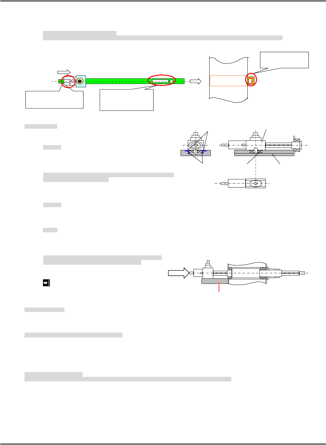
Assemble and insert the shaft.
Insert the shaft with the numbers of the shaft and ball spline tube to the same side and the joint of
the holder connected to the shaft to the outside.
シャフト部の組立て / シャフト挿入します。
シャフトの番号と、ボールスプライン筒側の番号を同じ側にし、シャフトに接続済みのホルダーについているジョイントを外側に向け挿入します。
组装轴部 / 插入轴。
将轴的编号和滚珠花键筒侧的编号向同一个方向,将安装在已连接到轴上的支架的接头向外侧插入。
9. Grease the nozzle shaft rotation stopper.
ノズル軸回り止め部
吸嘴轴旋转停止部
⑥
Grease
グリス塗布
涂敷润滑脂
Check that the sliding and roller surfaces of the
plate, housing and bearing are greased.
プレートに対してハウジングとの摺動面およびベアリングとの転がり面に、グリ
スが塗布されていることを確認します。
对于板进行确认,与盒之间的往返移动面以及轴承之间的滚动面,润滑脂是否已被
涂敷。
Grease: Panasonic LCG100
使用グリス
使用润滑脂
⑦
Check sliding.
摺動確認
确认往返移动
After assembling the plate, check the sliding resistance (maximum) in a horizontal posture.
Position the shaft on the plate for measurement.
プレートを組付けた後、水平状態で摺動抵抗値
(
最大値
)
を確認します。
測定は、測定軸をプレート上方に配置して行ってください。
组装板后,在水平状态下确认往返移动的抵抗值
(
最大值
)
。
将测定轴配置于板的上方,进行测量。
2 N
10. Assemble related parts.
周辺部を組み立てます。
组装周边部。
11. Attach the coupling between the ball spline and Z-axis ball screw.
ボールスプラインの、ボールネジの連結部を取り付けます。
安装滚珠花键的滚珠丝杠的连接部。
12. Check the sliding resistance of the nozzle holder.
Remove then reattach the springs of the nozzle holder and push the holder upwards. Then, release the
holder and confirm that it moves under gravity to the bottom dead center.
ノズルホルダの摺動確認をします。
ノズルホルダのバネを外してセットし、上に持ち上げた状態から放したときに、自重で下死点まで移動することを確認します。
确认吸嘴支架的往返移动。
取下吸嘴支架的弹簧,在将其安装后,从往上面顶起的状态下让其自动落下时,确认吸嘴支架是否因自己重量移动到下死点。
Lock the screw lightly while pushing
the shaft against the housing.
Center line of the
lock screw and hole
No. must be ali
g
ned.
Lock the screw on the
L-shaped side lightly.
Ball spline tube
side No.
Slidin
g
surface
Roller surface
Housing
Plate Bearing
Plate
F