NPM-D3维修手册.pdf - 第183页
NPM-D3 Service Manual 5.5 Light Weight 16-Nozzle Hea d EJM6D3-MB-05SM-00( 編集中 ).DOC Page 5-55 Fig. 1 3. Push the pulley against the bearing so that the bearin g will be completely inserted to touch the bottom surface of …
NPM-D3
Service Manual
5.5 Light Weight 16-Nozzle Head
Page 5-54 EJM6D3-MB-05SM-00(
編集中
).DOC
-axis Motor Attaching
軸モータの取り付け
轴电机的安装
24.
1. Assemble the
-axis motor in the reverse order in ‘
-axis Motor Detaching’. (Fig. 1)
前述の
‘
軸モータの取り外し
’
とは、ほぼ逆の手順で
軸モータ部を組み立てます。
(Fig. 1)
用与前述的
‘
轴电机的拆卸
’
大致相反的步骤组装
轴电机部分。
(Fig. 1)
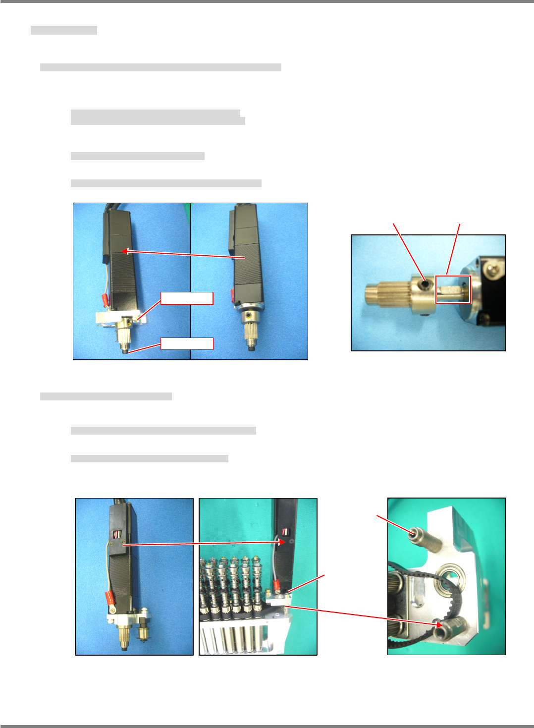
①
Insert the pulley into the motor shaft and lightly tighten the lock screw (2-M4x4).
Make sure that the D-cut part of the motor shaft is aligned with the lock screw. (Fig. 2)
モータ軸にプーリを挿入し止めねじ
(2-M4 x 4)
を仮締めします。
モータ軸の
D
カットと止めねじの位置を一致させること。
(Fig. 2)
将皮带轮插到电机轴上后用固定螺丝
(2-M4 x 4)
作临时固定。
须使电机轴的
D
切割部与固定螺丝的位置相一致。
(Fig. 2)
②
Tighten the bolt (M2.5x5) at the end of the motor shaft.
モータ軸先端のボルト
(M2.5 x 5)
を締め付けます。
拧紧电机轴端部的螺栓
(M2.5 x 5)
。
③
Attach the motor with the bolt (2-M3x10) to the motor mounting plate.
モータ取り付けプレートにボルト
(2-M3 x 10)
でモータを取り付けます。
用螺栓
(2-M3 x 10)
将电机装到电机安装板上。
2. Attach the
-axis motor to the
unit. (Fig. 3)
ユニットに
軸モータ部を取り付けます。
(Fig. 3)
将
轴电机部分装到
装置上。
(Fig. 3)
①
The motor mounting plate is located by the post. (Fig. 4)
モータ取り付けプレートは、ポストで位置決めされています。
(Fig. 4)
电机安装板是用柱来定位的。
(Fig. 4)
②
Keep the tension pulley of the
belt loose.
ベルトのテンションプーリは緩めたままにしておきます。
让
皮带的张力轮保持在松开的状态。
‘
Belt Replacement’.
Fig. 4 Fig. 3
Post
2-M3 x 12
Fig. 2
D-cut
2-M4
4
Fig. 1
M2.5
5
2-M3
10
NPM-D3
Service Manual
5.5 Light Weight 16-Nozzle Head
EJM6D3-MB-05SM-00(
編集中
).DOC Page 5-55
Fig. 1
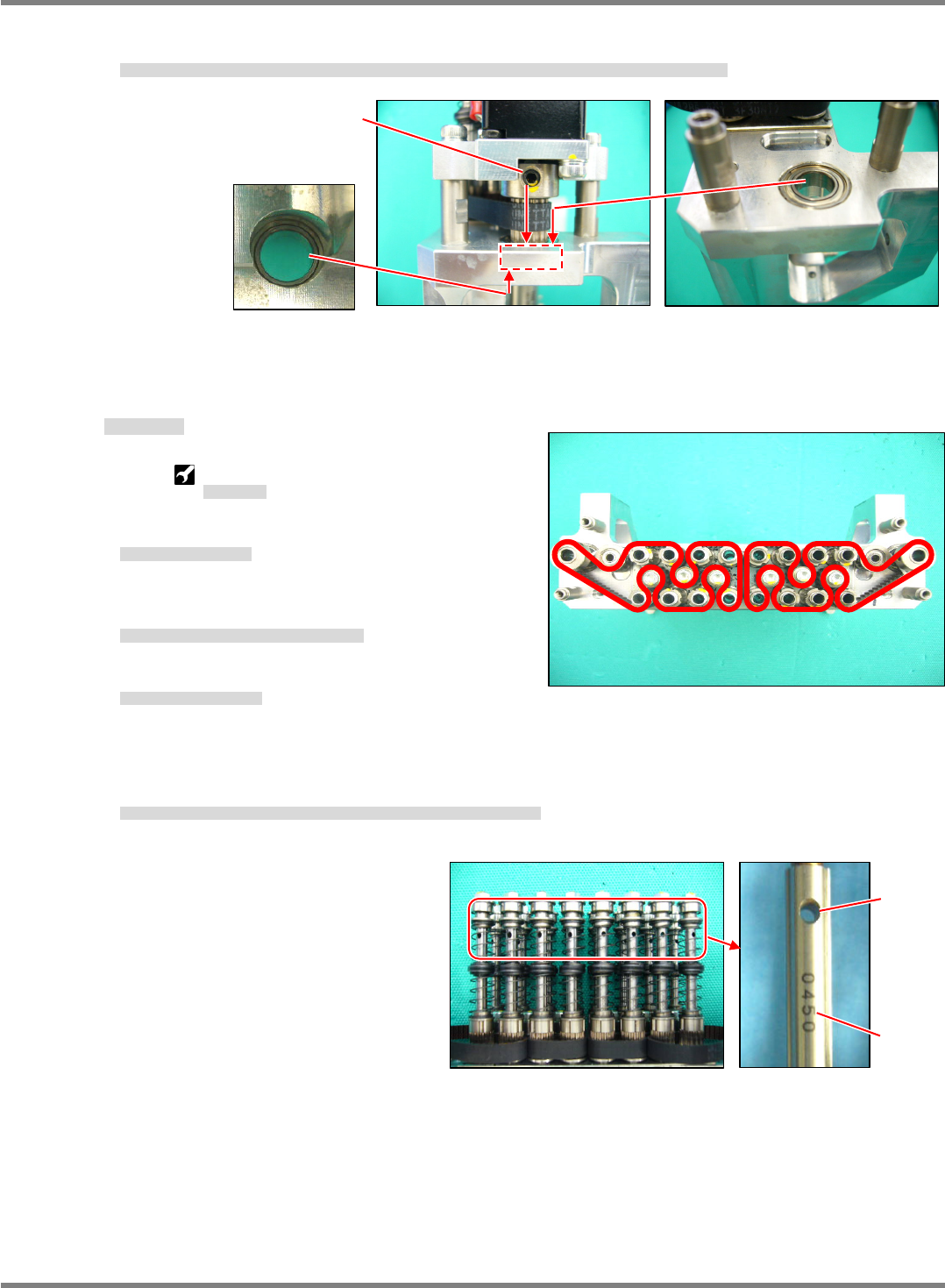
3. Push the pulley against the bearing so that the bearing will be completely inserted to touch the bottom
surface of the hole, and securely tighten the lock screw (2-M44). (Fig. 5)
ベアリングが穴の底面に完全に挿入されるように、プーリをベアリングに押し当て、止めねじ
(2-M4
4)
を本締めします。
(Fig. 5)
将皮带轮推靠在轴承上,使轴承完全插入到孔的底面,然后用固定螺丝
(2-M4
4)
正式固定住。
(Fig. 5)
Belt Replacement
ベルトの交換
皮带的更换
Sonic tension-meter:
N510008902AA
超音波張力計
超声波张力计
4. Replace the
-axis belt.
軸のベルトを交換します。
更换
轴的皮带。
5. Check the route of the belt and thread the belt into
the rollers. (Fig. 1)
ベルトの経路を確認してベルトを掛けます。
(Fig. 1)
确认皮带的路径后挂上皮带。
(Fig. 1)
6. Attach the
-axis motor.
軸モータ部を取り付けます。
安装
轴电机。
‘
-axis Motor Attaching’.
7. Check that the marking No. on the shafts and holes of the ball splines are oriented in the same direction.
(Fig. 2)
ボールスプラインのシャフトの刻印
No.
と穴が同じ方向であることを確認します。
(Fig. 2)
确认滚珠花键的轴的刻印
No.
与孔应在相同的方向上。
(Fig. 2)
Fig. 5
2-M4
4
Fig. 2
1.6
Marking
NPM-D3
Service Manual
5.5 Light Weight 16-Nozzle Head
Page 5-56 EJM6D3-MB-05SM-00(
編集中
).DOC
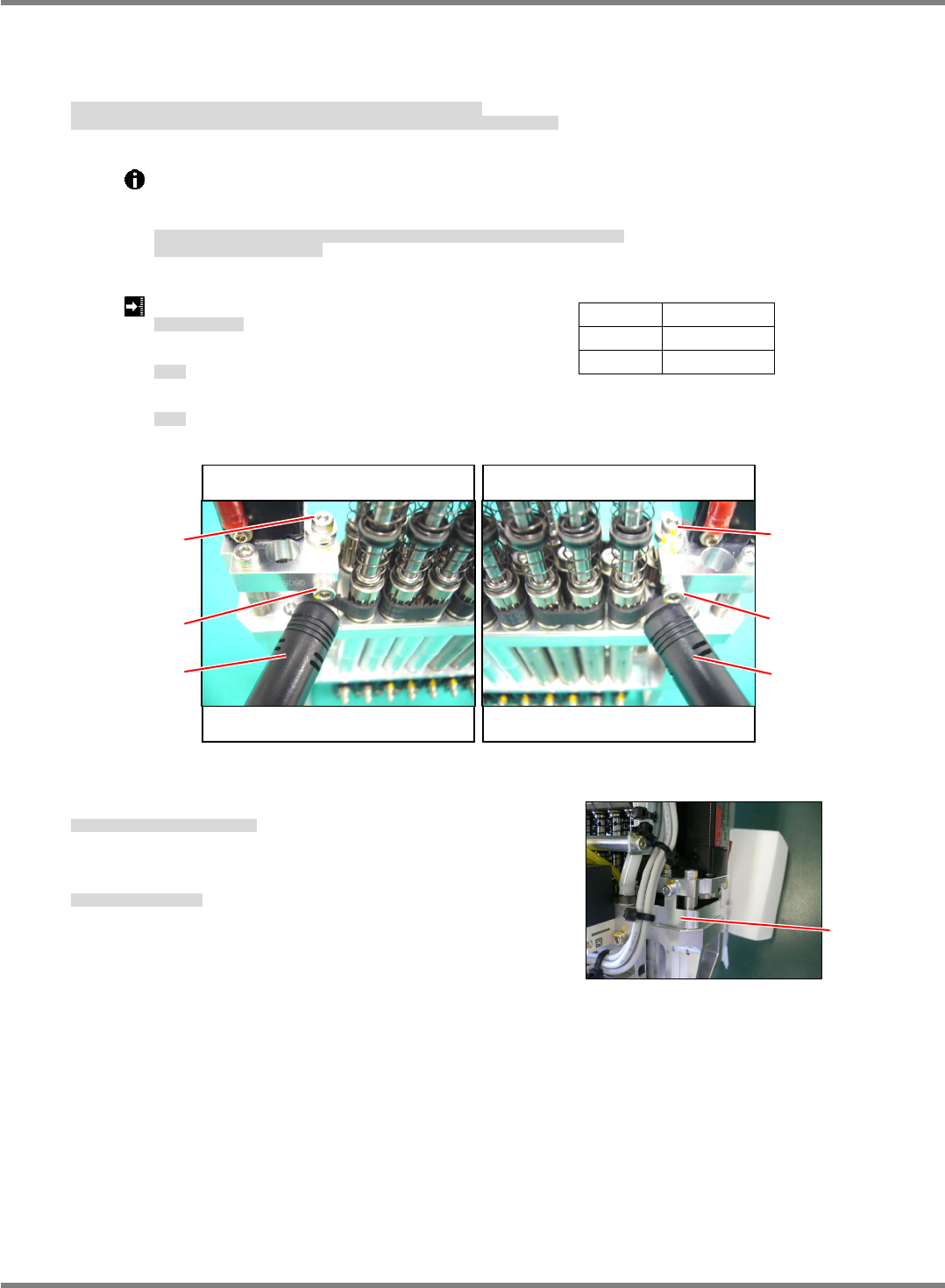
8. Measure the tension at six points for a single turn of the belt and obtain the average, maximum and
minimum values.
Adjust the tension and tighten the bolt (M3x10) of the tension roller at the position of the reference value.
(Fig. 3)
ベルト
1
回転中の
6
か所でテンションを測定し、平均値、最大値、最小値を求めます。
テンションを調整し、基準値となる位置でテンションローラ固定のボルト
(M3 x 10)
を締めます。
(Fig. 3)
测量皮带一周中的
6
处的张力,求得平均值、最大值、最小值。
调整张力,在能达到标准值的位置处拧紧张力滚轮的固定螺栓
(M3 x 10)
。
(Fig. 3)
Inserting the bolt (M3x6) into the block of the tension roller makes the tension adjustment
easy.
Remove the bolt after making the adjustment.
テンションローラのブロックにボルト
(M3 x 6)
を挿入すると、テンションの調整が容易に行えます。
調整後はボルトを外してください。
如在张力滚轮的块中插入螺栓
(M3 x 6)
,张力的调整就比较容易进行。
调整后请拆下螺栓。
belt tension: 14
2 N (Average value)
ベルトテンション
皮带张力
Maximum value: 19 N
最大値
最大值
Minimum value: 9 N
最小値
最小值
9. Attach the
belt cover. (Fig. 4)
ベルトカバーを取り付けます。
(Fig. 4)
装上
皮带的盖。
(Fig. 4)
10. Attach the
unit.
ユニットを取り付けます。
安装
装置。
‘5.5.3
Unit Detaching / Attaching’.
Span 31 mm
Width 6 mm
Mass
1.3
g
/m
Fig. 3
Nozzles No. 9 to 12 Nozzles No. 13 to 16
M3
10
Sonic
tension-mete
r
Sonic
tension-meter
M3
10
Nozzles No. 1 to 4 Nozzles No. 5 to 8
M3
6
M3
6
Fig. 4
Cover