NPM-D3维修手册.pdf - 第180页
NPM-D3 Service Manual 5.5 Light Weight 16-Nozzle Hea d Page 5-52 EJM6D3-MB-05SM-00( 編集中 ).DOC 4. Detach the -axis unit. (Fig. 3) 軸ユニット部を取り外します。 (Fig. 3) 卸下 轴装置。 (Fig. 3) ① The -axis unit is located by the positio…
NPM-D3
Service Manual
5.5 Light Weight 16-Nozzle Head
EJM6D3-MB-05SM-00(
編集中
).DOC Page 5-51
5.5.3
Unit Detaching / Attaching
ユニットの取り外し
/
取り付け
装置的拆卸
/
安装
Unit No.
N610096433AA
5.5.2 Valve Detaching /
Attaching
バルブ部の取り外し
/
取り付け
阀的拆卸
/
安装
Unit Detaching / Attaching
ユニットの取り外し
/
取り付け
装置的拆卸
/
安装
5.5.2 Valve Detaching /
Attaching
バルブ部の取り外し
/
取り付け
阀的拆卸
/
安装
22.
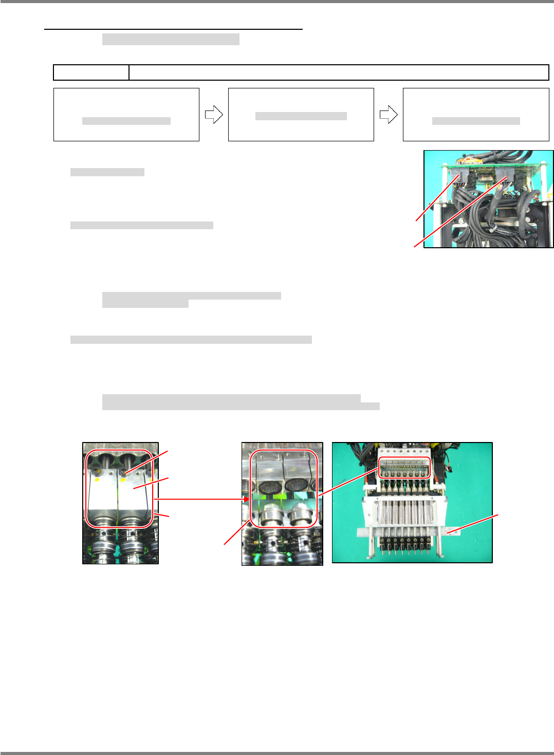
1. Detach the valves.
バルブ部を取り外します。
拆下阀。
‘5.5.2 Valve Detaching / Attaching‘.
2. Disconnect the connectors (CN1 / CN 3) of the
motor. (Fig. 1)
モータのコネクタ
(CN1 / CN3)
を抜きます。
(Fig. 1)
拔下
电机的连接器
(CN1 / CN3)
。
(Fig. 1)
=NOTE=
When disconnecting the connectors, be careful not to break
the wires.
Do not pull the cables.
コネクタを抜く時は、配線を切らないように注意してください。
ケーブルを引っ張らないこと。
拔连接器时,请注意不要切断配线。不可拉拽电缆。
3. Insert a scale into the housing at the end of the head and separate the fitting part from each other. (Fig. 2)
ヘッド先端のハウジング部にスケールなどを挟み、かみ合い部分を分離します。
(Fig. 2)
在贴装头端部的壳的部位用直尺等夹入,将咬合的部分分离开来。
(Fig. 2)
=NOTE=
The shafts of the Z-axis linear motor and ball spline are coupled with the plate.
Unseparated fitting part is can cause the shaft of the linear motor or ball spline to bend.
Z
軸リニアモータのシャフトとボールスプラインのシャフトはプレートで連結されています。
かみ合い部分を分離しないとリニアモータかボールスプラインのシャフトを曲げる原因になります。
Z
轴线性电机的轴与滚珠花键的轴是用板连结的。
如果不将咬合的部分分离,则可能会使线性电机或者滚珠花键的轴弯曲。
Fig. 1
CN1
CN3
Fig. 2
Must be
separated
Scale
Fitting part
Plate
M2
6
NPM-D3
Service Manual
5.5 Light Weight 16-Nozzle Head
Page 5-52 EJM6D3-MB-05SM-00(
編集中
).DOC
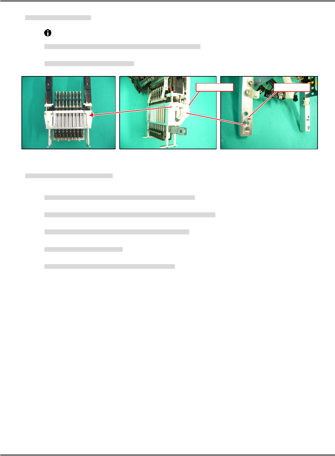
4. Detach the
-axis unit. (Fig. 3)
軸ユニット部を取り外します。
(Fig. 3)
卸下
轴装置。
(Fig. 3)
①
The
-axis unit is located by the positioning pin (2-
8x8) and secured with the bolt (4-M4x16).
軸ユニットは、規正ピン
(2-
3 x 8)
で位置決めされ、ボルト
(4-M4 x 16)
で固定されています。
轴装置是由定位销
(2-
3 x 8)
来定位的,并由螺栓
(4-M4 x 16)
固定的。
②
Cut the cable ties that bundle the wires and tubes as appropriate.
必要に応じて配線、配管の結束バンドを切断します。
必要时可切断配线、配管的绑扎带。
5. Reinstall the
unit in the reverse order in which it was detached.
前述とほぼ逆の手順で、
ユニットを取り付けます。
用与前述步骤大致相反的步骤安装
装置。
①
The
-axis unit is located by the positioning pin (2-
8 x 8) and secured with the bolt (4-M4 x 16).
ユニットは、規正ピン
(2-
3
8)
で位置決めされ、ボルト
(4-M4 x 16)
で固定されています。
装置是由定位销
(2-
3
8)
来定位的,并由螺栓
(4-M4 x 16)
固定的。
②
Make sure that the shafts of the Z-axis linear motor and ball spline will not interfere with each other.
Z
軸リニアモータのシャフトとボールスプラインのシャフトを干渉させないように注意してください。
请注意不要让
Z
轴线性电机的轴与滚珠花键的轴相干涉。
③
Couple the shafts of the Z-axis linear motor and ball spline with the plate.
Z
軸リニアモータのシャフトとボールスプラインのシャフトをプレートで連結します。
用板连结
Z
轴线性电机的轴和滚珠花键的轴。
④
Reconnect the connectors (CN1 / CN3) of the
motor.
モータのコネクタ
(CN1 / CN3)
を挿入します。
插入
电机的连接器
(CN1 / CN3)
。
⑤
Use new cable ties to secure the wires and tubes where the old cable ties were cut.
切断した結束バンドの個所は、新しい結束バンドで配線、配管を固定します。
对切断了绑扎带的部位,用新的绑扎带将配线、配管固定住。
Fig. 3
2-
3 x 8
4-M4 x 16
NPM-D3
Service Manual
5.5 Light Weight 16-Nozzle Head
EJM6D3-MB-05SM-00(
編集中
).DOC Page 5-53
5.5.4
-axis Motor / Belt Replacement
軸モータ・ベルトの交換
轴电机和皮带的更换
Unit No.
N610096433AA
5.5.3
Unit Detaching /
Attaching
ユニットの取り外し
/
取り付け
装置的拆卸
/
安装
-axis Motor / Belt Replacement
軸モータ・ベルトの交換
轴电机和皮带的更换
5.5.3
Unit Detaching /
Attaching
ユニットの取り外し
/
取り付け
装置的拆卸
/
安装
-axis Motor Detaching
軸モータの取り外し
轴电机的拆卸
23.
1. Detach the
unit.
ユニットを取り外します。
卸下
装置。
‘5.5.3
Unit Detaching / Attaching’
2. Detach the
belt cover from the
unit. (Fig. 1)
ユニットから
ベルトカバーを取り外します。
(Fig. 1)
从
装置上拆下
皮带盖。
(Fig. 1)
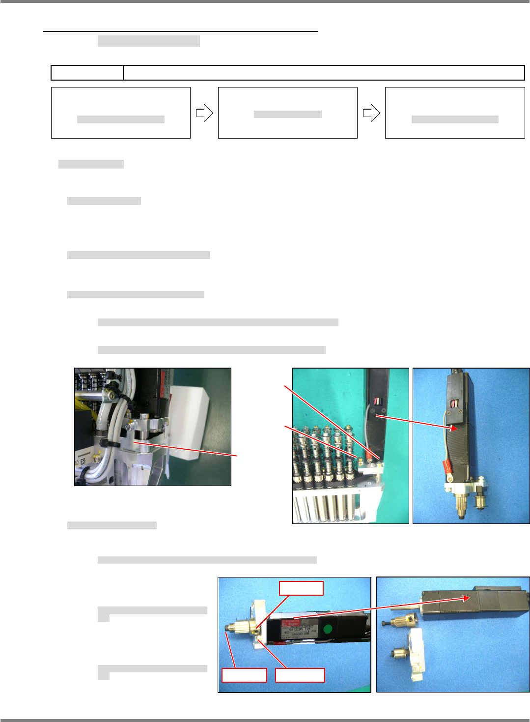
3. Detach the -axis motor from the
unit. (Fig. 2)
ユニットから
軸モータ部を取り外します。
(Fig. 2)
从
装置上拆下
轴电机部分。
(Fig. 2)
①
Loosen the bolt (M3
10) from the block of the tension pulley and ease the tension in the
-axis belt.
テンションプーリのブロックのボルト
(M3
10)
を緩め
軸ベルトのテンションを緩めます。
松开张力轮的块的螺栓
(M3
10)
,松开
轴皮带的张力。
②
Remove the bolt (2-M3
12) of the
-axis motor installation plate and detach the motor.
軸モータ取り付けプレートのボルト
(2-M3
12)
を外し、モータ部分を取り外します。
拆下
轴电机安装板的螺栓
(2-M3
12)
,拆下电机部分。
4. Disassemble the motor into single pieces. (Fig. 3)
モータ単体に分解します。
(Fig. 3)
分解成电机单体。
(Fig. 3)
①
Remove the bolt (2-M3
10) of the motor mounting plate and detach the motor.
モータ取り付けのプレートからボルト
(2-M3
10)
を外し、モータを取り外します。
从安装电机的板上拆下螺栓
(2-M3
10)
,取下电机。
②
Remove the bolt
(M2.5
5) at the end of
the motor shaft.
モータ軸先端のボルト
(M2.5
5)
を外しま
す。
拆下电机轴端部的螺栓
(M2.5
5)
。
③
Loosen the lock screw
(2-M4
4) and detach the
pulley.
止めねじ
(2-M4
4)
を緩めプーリを外しま
す。
松开固定螺丝
(2-M4
4)
后拆下皮带轮。
Fig. 2
2-M3 x 12
M3 x 10
Fig. 1
Cover
Fig. 3
2-M4 x 4
2-M3 x 10
M2.5 x 5