NPM-D3维修手册.pdf - 第190页
NPM-D3 Service Manual 5.5 Light Weight 16-Nozzle Hea d Page 5-62 EJM6D3-MB-05SM-00( 編集中 ).DOC 10. Insert the holder into the shaft and lightly tighten the lock screw (2-M2.5x3). (Fig. 10) シャフトにホルダを挿入し、止めねじ (2-M2.5 3) を…
NPM-D3
Service Manual
5.5 Light Weight 16-Nozzle Head
EJM6D3-MB-05SM-00(
編集中
).DOC Page 5-61
Fig. 9
Housing
Holder insertion
shaf
t
Bearing
Shaf
t
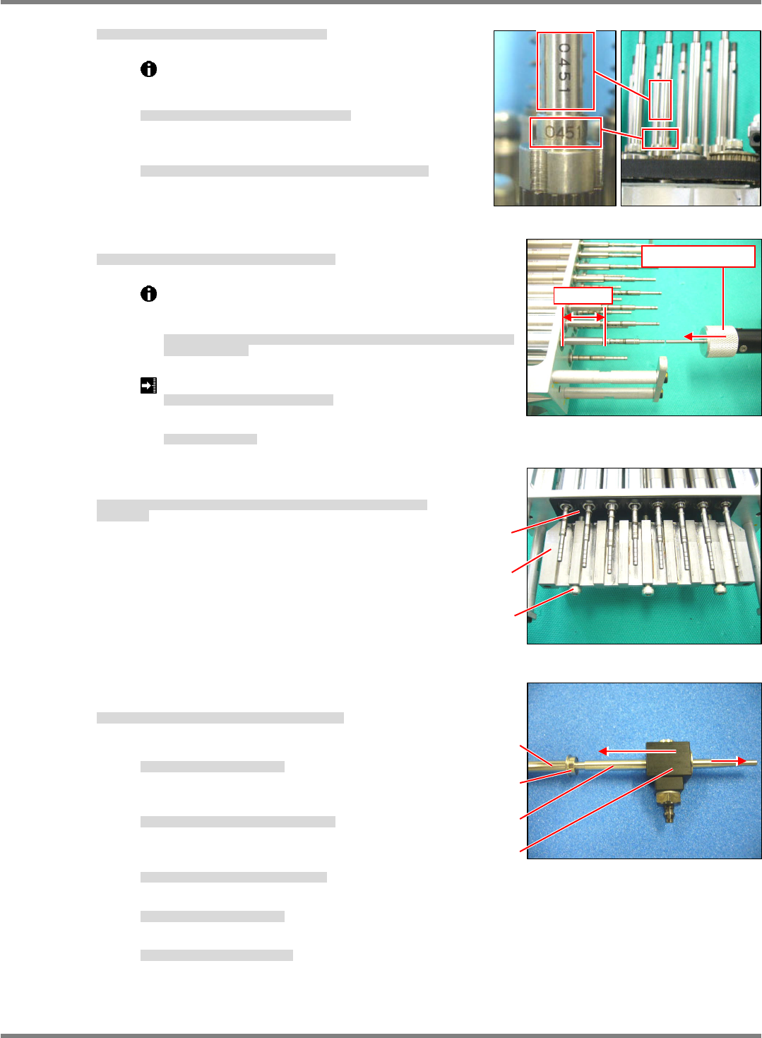
6. Insert the shaft into the nut of the ball spline. (Fig. 6)
ボールスプラインのナットにシャフトを挿入します。
(Fig. 6)
将轴插入滚珠花键的螺母中。
(Fig. 6)
①
Make sure that the marking Nos. on the nuts and
shafts are oriented in the same direction.
ナットとシャフトの刻印
No
と方向を一致させること。
须使螺母和轴的刻印
No.
方向一致。
②
Do not wipe grease off or apply it to the shaft of the
ball spline.
ボールスプラインのシャフト部のグリスのふき取りや塗布は行わないこと。
不可对滚珠花键的轴部进行润滑脂的擦去或涂抹。
7. Check the sliding resistance of the shafts of the ball spline. (Fig. 7)
ボールスプラインのシャフトの摺動抵抗を確認します。
(Fig. 7)
确认滚珠花键的轴的滑动阻抗。
(Fig. 7)
Keep the shafts horizontal and push the shafts with the
push-pull gauge, and measure the sliding resistance
within the range of 25 mm.
ボールスプラインを水平に置き、プッシュプルゲージでシャフトを押し、
25 mm
の範囲で摺
動抵抗を測定します。
将滚珠花键水平放置,用推拉规推动轴,测量
25 mm
范围的滑动阻抗。
Sliding resistance:
0.2 N
ボールスプラインのシャフトのスライド抵抗
滚珠花键的轴的滑动阻抗
Fluctuations in sliding resistance:
0.1 N
スライド抵抗のばらつき
滑动阻抗的偏差
8. Insert the plate for holding the bearing and lightly
tighten the housing guide plate. (Fig. 8)
ベアリング押さえのプレートを挟み、ハウジングをガイドしているプレートを仮締めし
ます。
(Fig. 8)
在夹住轴承压板的情况下,对壳的导向板进行临时固定。
(Fig. 8)
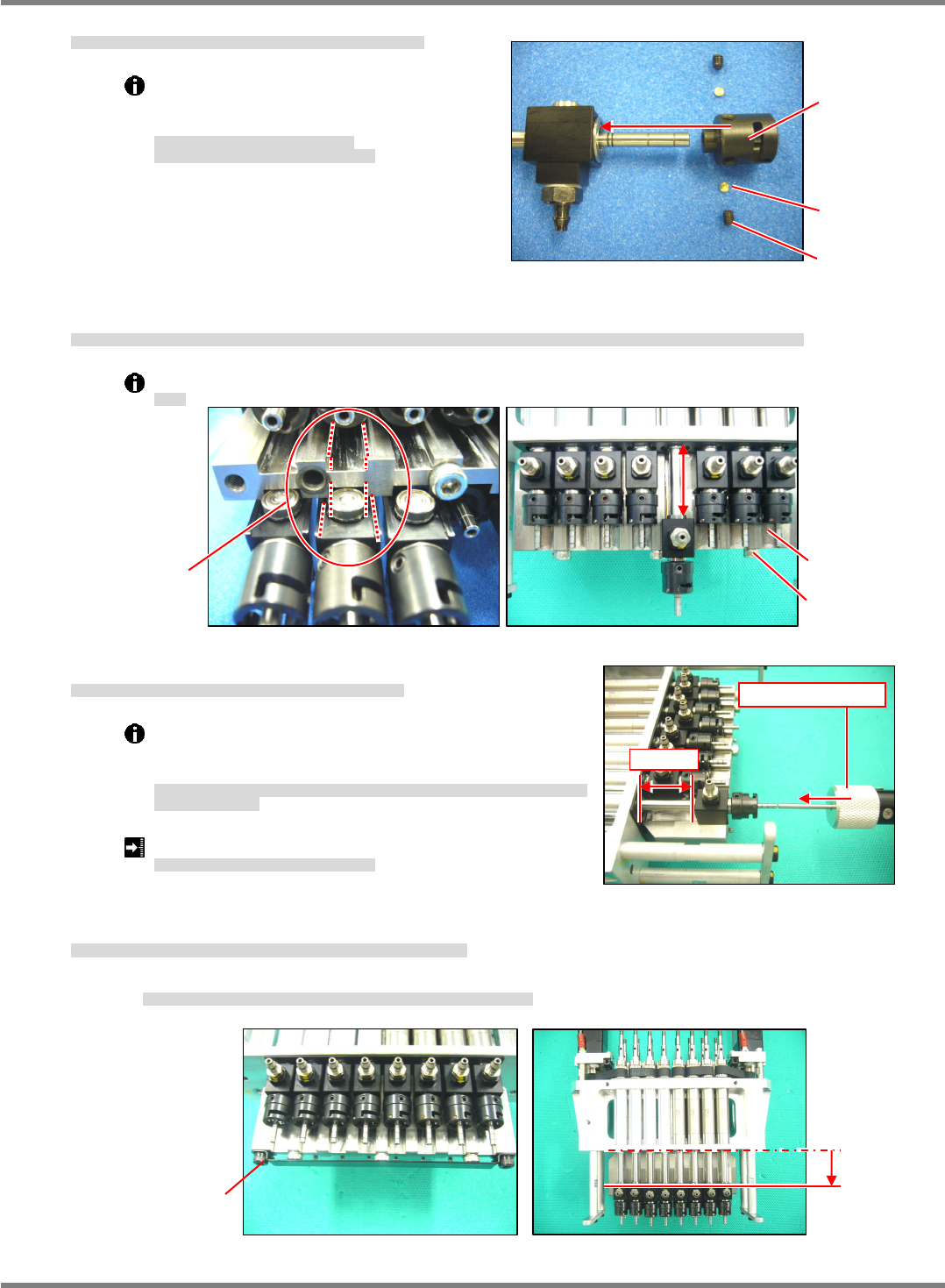
9. Insert the housing into the shaft of the ball
spline. (Fig. 9)
ボールスプラインのシャフトにハウジングを挿入します。
(Fig. 9)
将壳插到滚珠花键的轴上。
(Fig. 9)
①
Insert the bearing into the shaft.
シャフトにベアリングを挿入します。
将轴承插到轴上。
②
Insert the housing insertion shaft into the
shaft.
シャフトにハウジング挿入シャフトを挿入します。
将插壳的轴插到轴上。
③
Insert the housing until it reaches the
bearing.
ハウジングをベアリングの位置まで挿入します。
将壳插到轴承的位置为止。
④
Remove the housing insertion shaft.
ハウジング挿入シャフトを抜きます。
拔下插壳的轴。
⑤
Insert the bearing into the housing.
ハウジングにベアリングを挿入します。
将轴承插入壳中。
Fig. 6
25 mm
Fig. 7
Push-pull gauge
Fig. 8
Plate
Plate
3-M3 x 40
NPM-D3
Service Manual
5.5 Light Weight 16-Nozzle Head
Page 5-62 EJM6D3-MB-05SM-00(
編集中
).DOC
10. Insert the holder into the shaft and lightly tighten the lock screw (2-M2.5x3). (Fig. 10)
シャフトにホルダを挿入し、止めねじ
(2-M2.5
3)
を仮締めします。
(Fig. 10)
将支架插到轴上,用固定螺丝
(2-M2.5
3)
进行临时固定。
(Fig. 10)
Pieces are incorporated at the end of the
lock screw.
Be careful not to lose them.
止めねじの先端にピースが入っています。
ピースを紛失しないように注意してください。
在固定螺丝的端部有一个小块。
请注意不要使小块丢失。
11. Apply grease to the contact surface of the plate housing and outer ring of the bearing, and securely tighten
the plate where all shafts slide smoothly. (Fig. 11)
プレートのハウジングとベアリング外輪の接触面にグリスを塗布し、すべてのシャフトがスムーズにスライドする位置でプレートを本締めします。
(Fig. 11)
在板与壳及轴承外轮的接触面处涂抹润滑脂,在所有轴都能滑顺地滑动的位置处将板正式固定住。
(Fig. 11)
Grease: Panasonic LCG100
グリス
润滑脂
12. Check the sliding resistance of the shafts when attaching the plate.
プレート取り付け時のシャフトのスライド抵抗を確認します。
(Fig. 12)
安装板时要确认轴的滑动阻抗。
(Fig. 12)
Keep the shafts horizontal and push the shafts with the
push-pull gauge, and measure the sliding resistance
within the range of 25 mm.
ボールスプラインを水平に置き、プッシュプルゲージでシャフトを押し、
25 mm
の範囲で摺
動抵抗を測定します。
将滚珠花键水平放置,用推拉规推动轴,测量
25 mm
范围的滑动阻抗。
Sliding resistance when attaching the plate:
0.5 N
プレート取り付け時のシャフトのスライド抵抗
安装板时的轴的滑动阻抗
13. Attach the cover and check that the shafts fall with their own weight. (Fig. 13)
カバーを取り付け、すべてのシャフトが自重で下降することを確認します。
(Fig. 13)
装上盖,确认所有的轴能以自重下降。
(Fig. 13)
The bolts (2-M3
6) for securing the cover and spring washer must be black color.
カバーを取り付けるボルト
(2-M3
6)
とスプリングワッシャは黒色を使用すること。
安装板的螺栓
(2-M3
6)
和弹簧垫圈要使用黑色的。
Fig. 10
Holder
Piece
M2.5 x 3
Fig. 11
3-M3 x 40
Plate
A
pply grease.
Fig. 13
Lower
2-M3 x 6
Fig. 12
25 mm
Push-pull gauge
NPM-D3
Service Manual
5.5 Light Weight 16-Nozzle Head
EJM6D3-MB-05SM-00(
編集中
).DOC Page 5-63
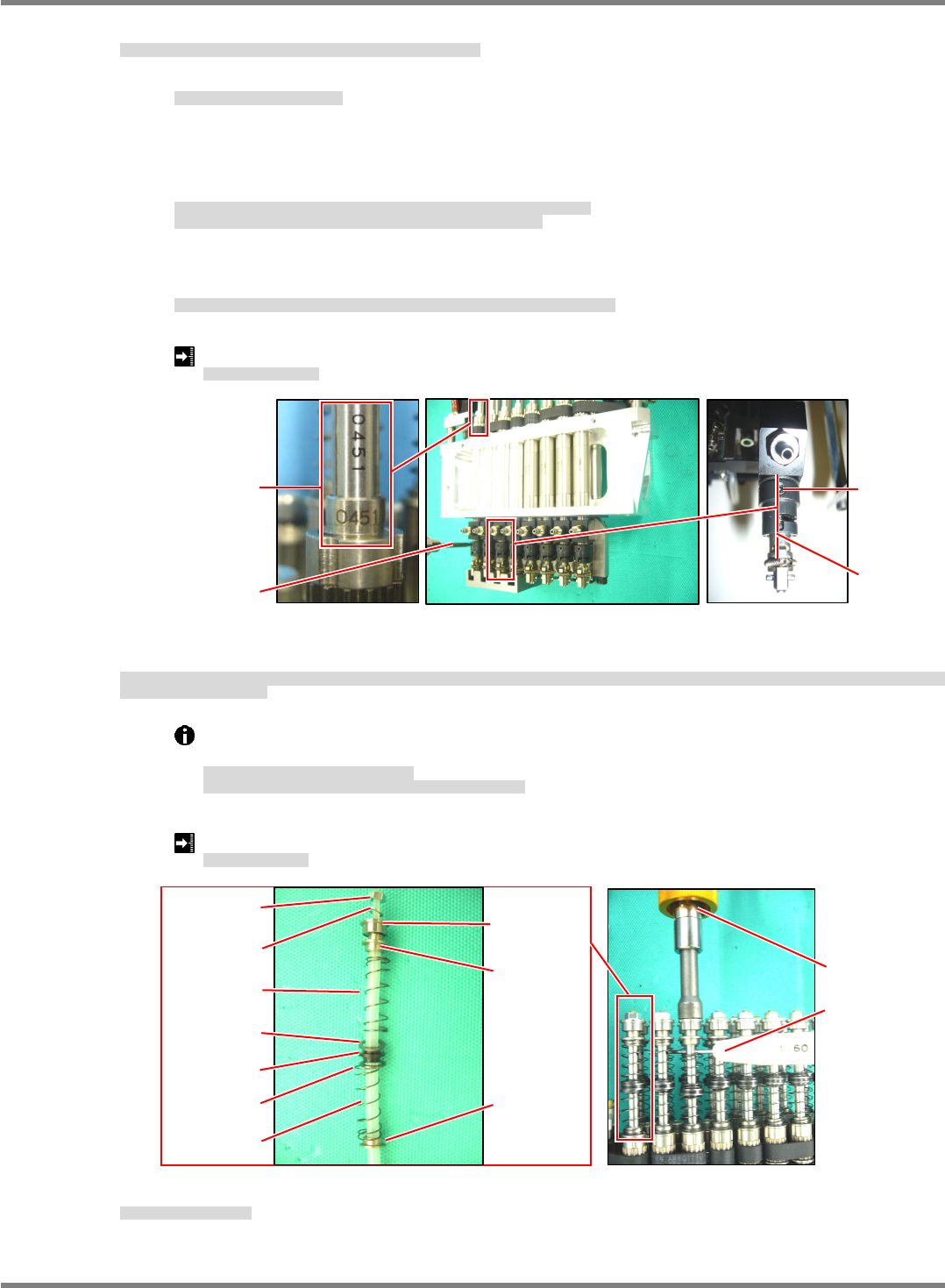
14. Insert the nozzle holder
positioning into the holder and perform positioning of the holder. (Fig. 14)
ホルダにノズルホルダ
規正を挿入し、ホルダの位置決めをします。
(Fig. 14)
将吸嘴支架的
定位工具插入支架中,进行支架的定位。
(Fig. 14)
①
Face the markings on the shafts outwards.
シャフトの刻印を外向きにします。
要使轴的刻印朝外。
②
Insert the nozzle holder
positioning into the eight nozzle holders and lightly tighten the lock screw
of the holder.
Make sure that the marking of the ball spline, lock screw of the holder and vertical groove are facing
the front side.
ノズルホルダ
規正を
8
本のノズルホルダに挿入し、ホルダの止めねじを仮締めします。
ボールスプラインの刻印とホルダの止めねじ、縦溝が正面を向いていること。
将吸嘴支架
定位工具插入
8
根吸嘴支架中,临时固定住支架的固定螺丝。
滚珠花键的刻印和支架的固定螺丝、纵沟都要朝向正面。
③
Detach the nozzle holder
positioning and securely tighten the lock screw (2-M2.5x3) of the holder
with a torque driver.
ノズルホルダ
規正を外し、ホルダの止めねじ
(2-M2.5 x 3)
をトルクドライバで本締めします。
取下吸嘴支架
定位工具,用扭矩螺丝刀将支架的固定螺丝
(2-M2.5 x 3)
正式拧紧。
Lock screw tightening torque: 30
3 N
cm
止めねじ締め付けトルク
固定螺丝的拧紧扭矩
15. Insert the collar, spring, washer and guide carefully not to let the spring fly off, and insert the quenched pin
(
1.6 mm) into the hole of the shaft to stop turning, then tighten the nut with a torque driver.
スプリングを飛ばさないように注意して、カラー、スプリング、ワッシャ、ガイド、ガイドを入れ、焼入れピン
(
1.6 mm)
をシャフトの穴に挿入して回り止めとし、ナットをト
ルクドライバで締め付けます。
在注意不要使弹簧跳掉的同时,放入轴环、弹簧、垫圈、导向环,将淬火销
(
1.6 mm)
插入轴的孔中进行止转,然后用扭矩螺丝刀拧紧螺母。
Make sure that the bearing and collar are orientated properly.
Insert the quenched pin (
1.6 mm) into the hole of the shaft to stop turning it.
ベアリング、カラーの向きに注意すること。
シャフトの周り止めには必ず焼入れピン
(
1.6 mm)
を使用すること。
请注意轴承、轴环的朝向。
对轴的止转必须使用淬火的销
(
1.6 mm)
。
Nut tightening torque: 80 N
cm
ナット締め付けトルク
螺母拧紧扭矩
16. Attach the
unit.
ユニットを取り付けます。
装上
装置。
‘5.5.3
Unit Detaching / Attaching’.
Fig. 14
Vertical
groove
Marking
Lock screw
Torque drive
r
Fig. 15
Nu
t
Bearing
Collar
Spring
Spring
CollarWashe
r
Guide
Washe
r
Torque driver
Quenched pin
Washe
r