NPM-D3维修手册.pdf - 第138页
NPM-D3 Service Manual 5.2 12-nozzle Head Page 5-10 EJM6D3-MB-05SM-00( 編集中 ).DOC Fig. 1 Top cove r Side cove r Front cove r Fig. 2 Moto r connecto r Encode r connecto r CN19 CN21 CN23 CN18 C N16 CN14 CN20 CN22 CN24 CN17 C…
NPM-D3
Service Manual
5.1 Head Unit
EJM6D3-MB-05SM-00(
編集中
).DOC Page 5-9
Fig. 1
Detach the
cover.
Mounting Head Drawer Connector
装着ヘッドドロアコネクタ
贴装头抽屉式连接器
Head drawer connector positioning jig:
ヘッドドロアコネクタ位置調整治具
头抽屉式连接器位置调整治具
6.
1. Detach the mounting head.
装着ヘッドを取り外します。
卸下贴装头。
‘5.1.1 Head Unit Detaching and Attaching’.
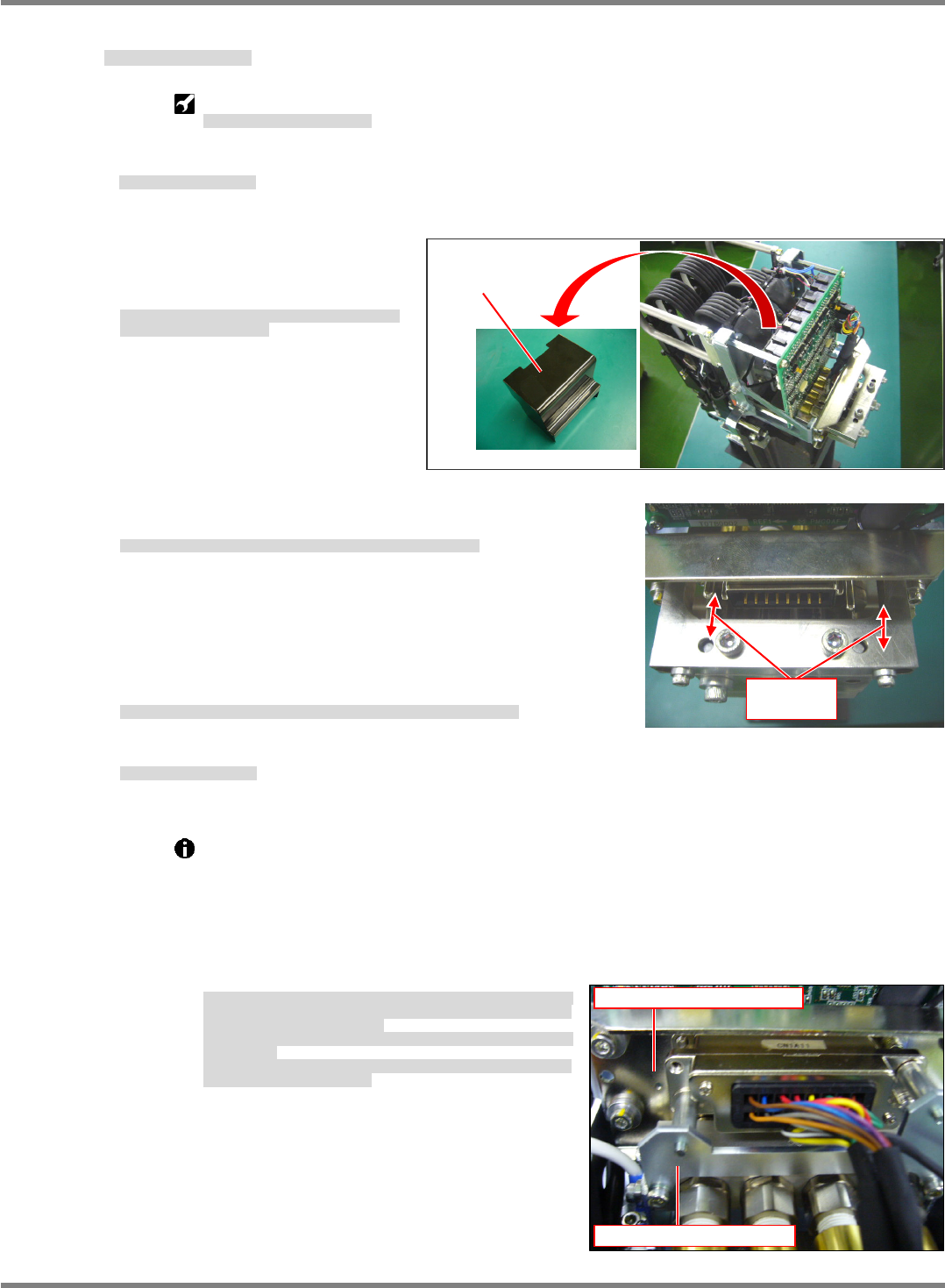
2. Attach the mounting head to the
head drawer connector positioning
jig and detach the cover. (Fig. 1)
装着ヘッドをヘッドドロアコネクタ位置調整治具に取り付
け、カバーを外します。(Fig. 1)
将贴装头安装在头抽屉式连接器位置调整治具上后,拆下盖。
(Fig. 1)
3. Adjust the position so that the pins of the jig fit in the holes of the
air coupler. (Fig. 2)
治具のピンとエアーカプラの穴が一致するように位置を調整します。(Fig. 2)
为了使治具的销和空气耦合器的孔一致,调整位置。(Fig. 2)
4. Detach the X-axis drawer connector positioning jig and attach the
upper cover of the connector.
X 軸側コネクタ位置調整治具を取り外し、接続コネクタ部の上部カバーを付けます。
卸下 X 轴抽屉式连接器位置调整治具后,安装连接器的上部盖。
5. Attach the mounting head.
装着ヘッドを取り付けます。
安装贴装头。
‘5.1.1 Head Unit Detaching and Attaching’.
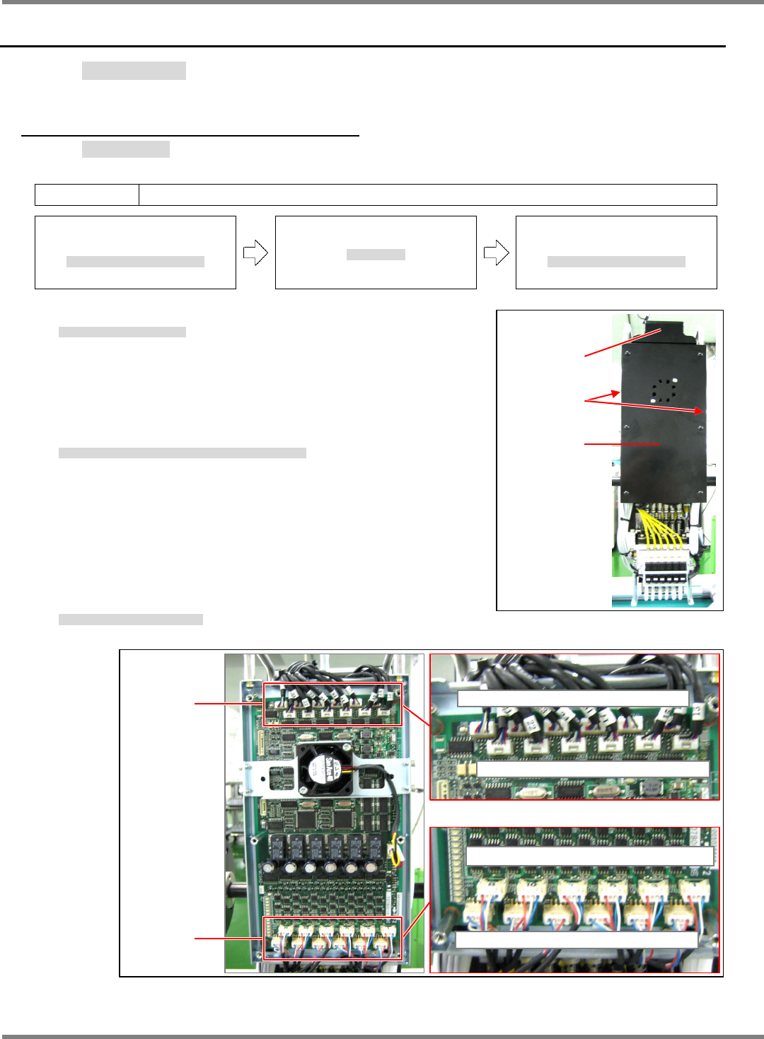
If the drawer connector positioning jig cannot be used as a reference point, use a connector
location on the front and rear X-axis side or head side that is not out of position as a
reference point, and align the connector with the position of the drawer connector on the
mating side. (Fig. 3)
Do not loosen the 4 drawer connectors on the front and rear X-axis or head at the same time.
Even without the positioning jig, connectors can be aligned with their mating side by using a
connector that is not out of position as a point of reference.
ドロアコネクタ接続治具が準備できない場合は、
FRONT
と
REAR
の
X
軸側か
ヘッド側で、コネクタの位置がずれていない個所を基準にし、相手側のドロア
コネクタの位置を合わせます。
(Fig. 3)
FRONT/REAR
と
X
軸
/
ヘッドの
4
か所のドロアコネクタを、同時に全て緩めな
いでください。
治具が無い場合でも、位置ズレしていない個所を基準にして、相手側のドロア
コネクタの位置合わせが可能です。
不能准备抽屉式连接器连接治具时,将
FRONT
和
REAR
的
X
轴侧或者头侧的连
接器的位置没有发生偏移的位置作为基准,调整对方侧的抽屉式连接器的位置。
(Fig. 3)
请不要同时拧松
FRONT/REAR
和
X
轴
/
头的
4
处的抽屉式连接器。
如果没有治具,也可以将没有发生位置偏移的位置作为基准,进行对方侧的抽屉
式连接器的位置的定位。
Fig. 2
Adjust the
positions.
Fig. 3
X-axis side drawer connector
Head side drawer connector
NPM-D3
Service Manual
5.2 12-nozzle Head
Page 5-10 EJM6D3-MB-05SM-00(
編集中
).DOC
Fig. 1
Top cove
r
Side cove
r
Front cove
r
Fig. 2
Moto
r
connecto
r
Encode
r
connecto
r
CN19 CN21 CN23 CN18 CN16 CN14
CN20 CN22 CN24 CN17 CN16 CN13
CN8 CN10 CN12 CN5 CN3 CN1
CN7 CN9 CN11 CN6 CN4 CN2
5.2 12-nozzle Head
12 ノズルヘッド
12 吸嘴头
5.2.1 Z-axis Motor Replacement
Z 軸モータ交換
Z 轴电机的交换
Unit No.
N610067507AA
5.1.1 Head Unit Detaching and
Attaching
ヘッドユニット取り外し
/
取り付け
头装置的拆卸和安装
5.2.1 Z-axis Motor Replacement
Z
軸モータ交換
Z
轴电机的交换
5.1.1 Head Unit Detaching and
Attaching
ヘッドユニット取り外し
/
取り付け
头装置的拆卸和安装
7.
1. Detach the head unit.
ヘッドユニットを取り外します。
卸下头装置。
‘5.1.1 Head Unit Detaching and Attaching’
2. Detach the covers from the top, sides and front of the head unit.
(Fig. 1)
ヘッドユニットの上面、側面、正面のカバーを外します。(Fig. 1)
拆下头装置上面、侧面、以及正面的盖。(Fig. 1)
3. Disconnect wiring from the Z-axis motor (Fig. 2)
Z 軸モータの配線を外します。(Fig. 2)
拆卸 Z 轴电机的配线。(Fig. 2)
NPM-D3
Service Manual
5.2 12-nozzle Head
EJM6D3-MB-05SM-00(
編集中
).DOC Page 5-11
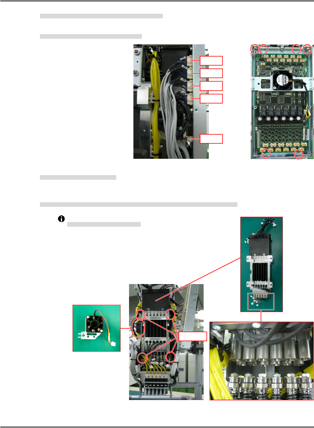
4. Disconnect wires (flow sensor and cooling fan) from the head unit side. (Fig. 3)
ヘッドユニット側面の流量センサと冷却ファンのコネクタを抜きます。(Fig. 3)
拔出头装置侧面的流量传感器和冷却扇的连接器。(Fig. 3)
5. Remove the board installation bolts (4-M3 x 8L / 2-M4 x 8L). (Fig. 4)
基板の取り付けボルト(4-M3×8)と(2-M4×8)を外します。(Fig. 4)
卸下基板安装螺栓 (4-M3×8) 和 (2-M4×8)。(Fig. 4)
6. Detach the cooling fan. (2-M4 x 10L button bolts).
冷却ファンを外します。(ボタンボルト 2-M410)
卸下冷却扇。(圆头螺栓 2-M410)
7. Remove the installation bolts (4-M5 x 20L) of the Z-axis linear motor. The shaft of the linear motor and the
spline shaft separate.
Z 軸リニアモータの、取り付けボルト(4-M520)を外し、リニアモータ部のシャフトと、スプラインシャフトを分離させます。
卸下 Z 轴线性电机的安装螺栓 (4-M520),将线性电机部的轴和花键轴分开。
Be careful not to bend the shafts.
シャフトを曲げないように注意してください。
请注意勿让轴发生弯曲。
Fig. 4
Fig. 3
CN34
CN35
CN36
CN37
CN28
Cooling fan
4-M5
20