NPM-D3维修手册.pdf - 第125页
NPM-D3 SERVICE MANUAL 4.6 Optional Units EJM6D3-MB-04SM-02.DOC Page 4-87 Clamp plate mounting bolt Fig. 2 Fig. 1 Block gau ge t = 117.5 mm Measure the top faces. (3) (2) (1) 75.5 mm Reference value Clamp Plate Height a…
NPM-D3
SERVICE MANUAL
4.6 Optional Units
Page 4-86 EJM6D3-MB-04SM-02.DOC
4.6.4 Board Holder Unit
基板ホルダユニット
基板支架装置
Unit No.
N610093412AA
4.6.5 Board Holder Unit
基板ホルダユニット
基板支架装置
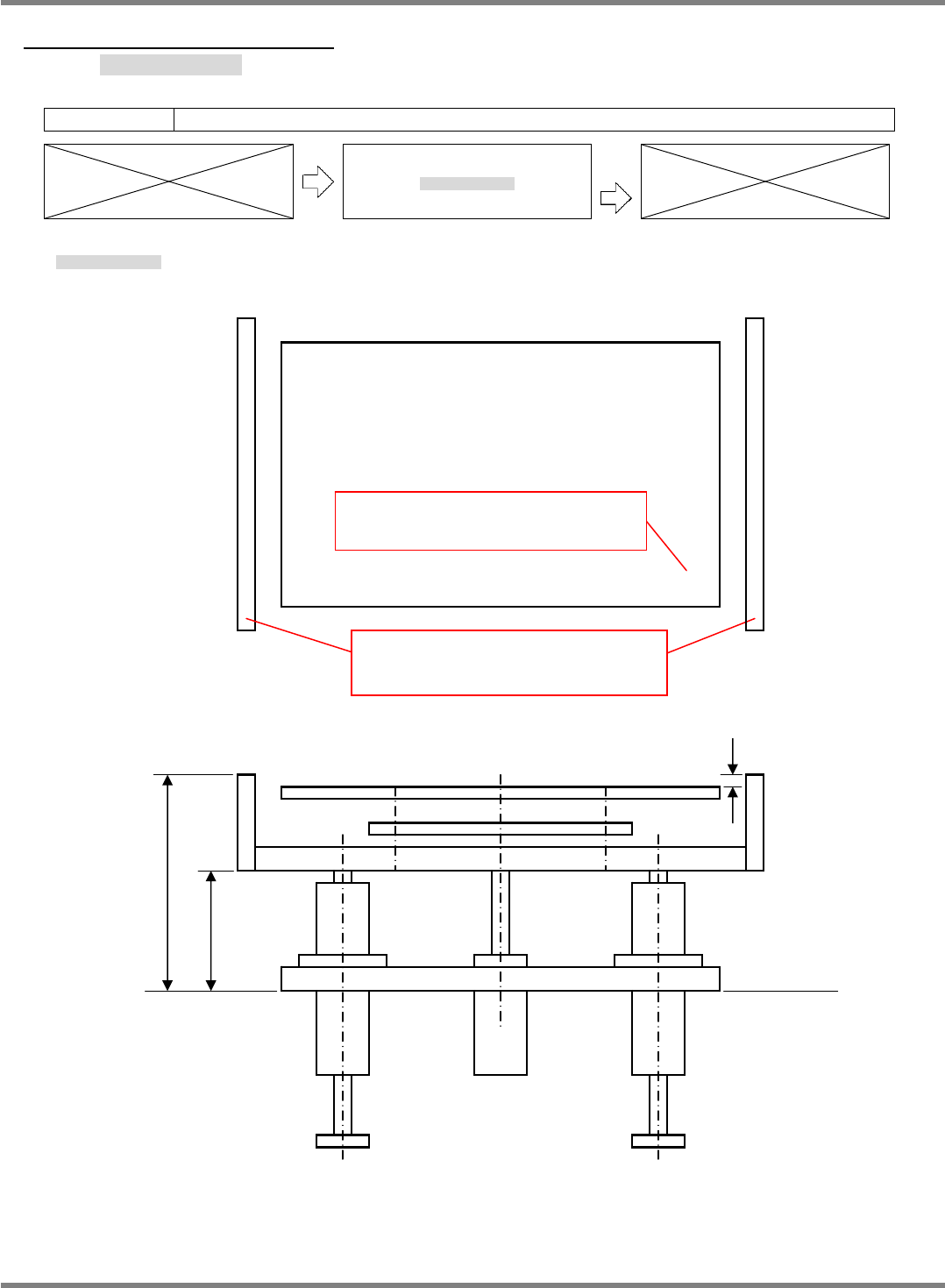
Outline Dimensions of Board Holder
基板ホルダの概略寸法
基板支架的概略尺寸
117.5
0.05 mm
CYL
75.5 mm
3.6
0.05 mm
Base plane
Support block planarity: Within 0.1 mm
Measure the height at (2), (3), (4), (5), (6)
and (7) as difference from that at (1).
Support plate planarity: 0.05 mm or below
Measure the height at (2), (3), (4), (5) and (6)
as difference from that at (1).
NPM-D3
SERVICE MANUAL
4.6 Optional Units
EJM6D3-MB-04SM-02.DOC Page 4-87
Clamp plate mounting bolt
Fig. 2
Fig. 1
Block gauge
t = 117.5 mm
Measure the top faces.
(3)
(2)
(1)
75.5 mm
Reference
value
Clamp Plate Height and Planarity
クランププレート高さ・平面度
夹板的高度和平面度
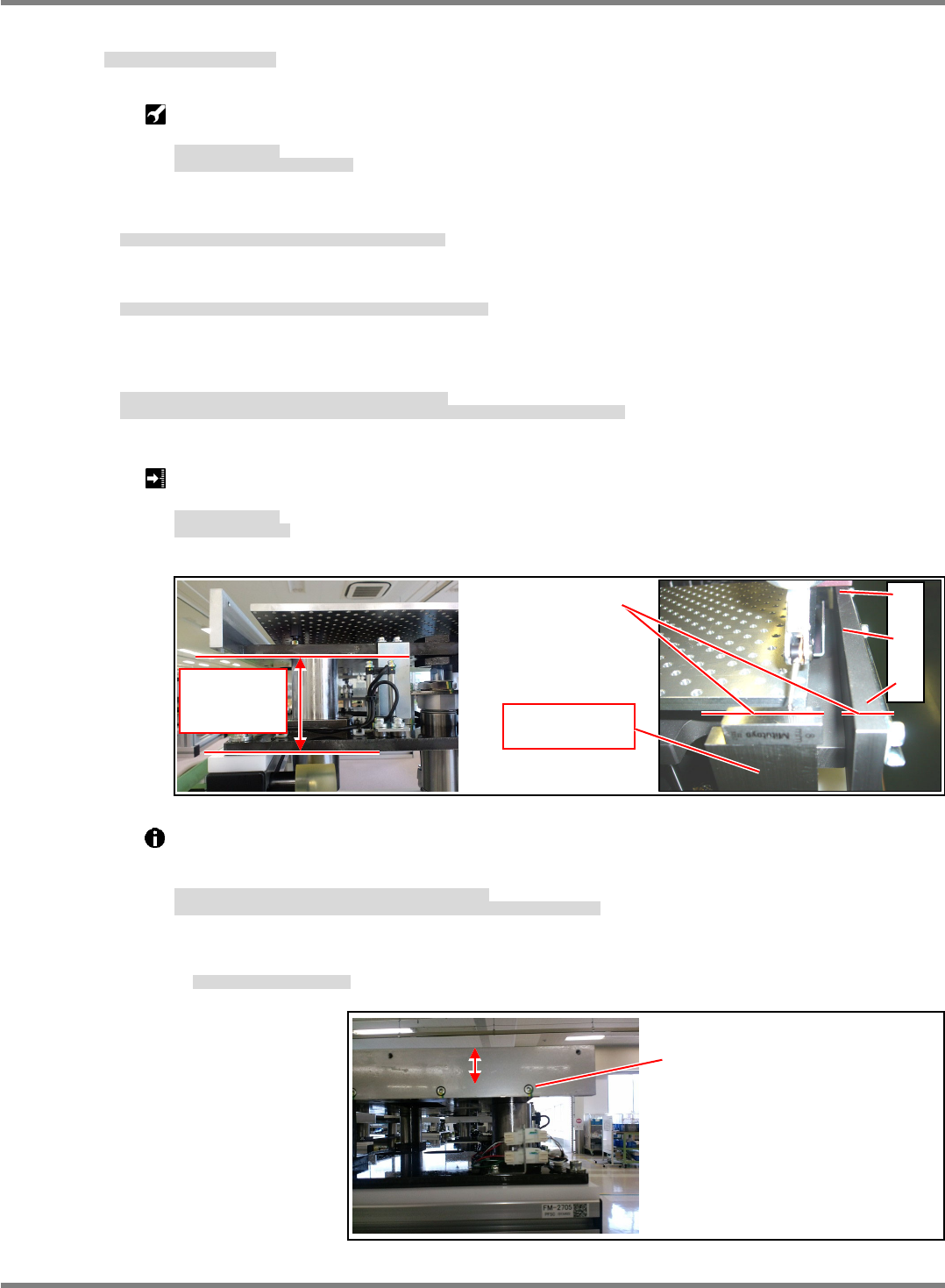
Block gauge set: 117.5 mm
Dial gauge & magnet stand
ブロックゲージセット
ダイヤルゲージ&マグネットスタンド
块规组件
千分表和磁性支架
15.
1. Stack block gauges to a height of 117.5 mm on the base plane of the main frame.
本体フレームのベース面に 117.5 mm のブロックゲージを置きます。
在主体架的基础面上放上 117.5 mm 的块规。
2. Attach a dial gauge via a magnet stand to the mounting head.
装着ヘッド部にマグネットスタンドを介してダイヤルゲージを取り付けます。
用磁性支架将千分表设置于贴装头部。
3. Measure the height at the top faces of the block gauges and the clamp plate. (Fig. 1)
Measure the both left and right plates at three positions each, six positions in all to check planarity.
ブロックゲージとクランププレートの上面を比較測定します。(Fig. 1)
プレート上面を基準に、左右のプレート上面の各 3 か所ずつ、計 6 か所を測定し、平面度を確認します。
测定比较块规与夹板的上平面。(Fig. 1)
以板的上平面为基准,测定左右板上平面的各 3 处,共计测定 6 处,确认平面度。
Clamp plate height: 117.5±0.05 mm
Clamp plate planarity:
0.05 mm
クランププレート高さ
クランププレート平面度
夹板高度
支撑板平面度
Adjust the height of the clamp plate (1) by the screw-in depth of the cylinder.
Adjust the planarity between the position (1) and the positions (2) to (6) by the position of the
clamp plate. (Fig. 2)
クランププレートの高さ
はシリンダのねじ込み量で調整します。
に対する
の平面度は、クランププレートの取り付け位置で調整します。
(Fig. 2)
夹板的高度
是由气缸的旋入量来调整的。
针对
的
的平面度是由夹板的安装位置来调整的。
(Fig. 2)
Perform measurement with the cylinder lower limit ON.
シリンダ下限 ON で作業のこと。
应在气缸下限 ON 时作业。
NPM-D3
SERVICE MANUAL
4.6 Optional Units
Page 4-88 EJM6D3-MB-04SM-02.DOC
Support Plate Height and Planarity
下受けプレート高さ・平面度
支撑板高度、平面度
The height of the support block is adjusted based on the clamp plate as reference.
Always finish the confirmation and adjustment of ’
Clamp Plate Height and Planarity’ in the
previous section.
下受け高さは、クランププレートが基準になります。
前項の
’
■クランププレート高さ・平面度
’
の確認と調整を終了しておくこと。
支撑高度是以夹板为基准的。
先要完成前项的
’
夹板的高度和平面度
’
的确认和调整。
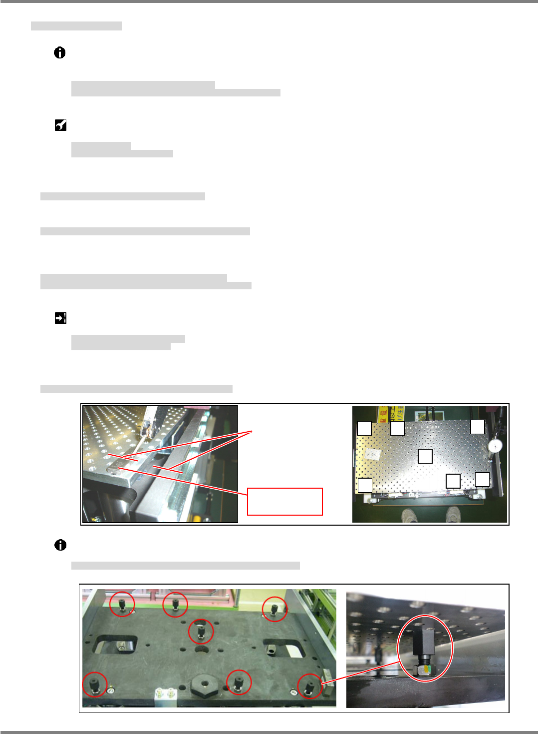
Block gauge set: 3.6 mm
Dial gauge & magnet stand
ブロックゲージセット
ダイヤルゲージ&マグネットスタンド
块规组件
千分表和磁性支架
16.
1. Place a block gauge 3.6 mm on the top surface of the support plate.
下受けプレート上面に 3.6mm のブロックゲージを置きます。
在支撑板上面放上 3.6 mm 的块规。
2. Attach a dial gauge via a magnet stand to the mounting head.
装着ヘッド部にマグネットスタンドを介してダイヤルゲージを取り付けます。
用磁性支架将千分表设置于贴装头部。
3. Measure the top faces of the block gauge and the clamp plate. (Fig. 1)
Measure at 4 positions ((1), (2), (4) and (5)) on the support plate based on the clamp plate as reference.
ブロックゲージとクランププレートの上面を比較測定します。(Fig. 1)
クランププレートを基準に、下受けプレートの 4 か所()を測定します。
测定比较块规与夹板的上平面。(Fig. 1)
以夹板为基准,测定支撑板的 4 处()。
Height difference between clamp plate and support block: 3.6±0.05 mm
Planarity of support plate: Within 0.1 mm
クランププレートと下受けブロックの段差
下受けプレート平面度
: 0.1 mm
以内
夹板与支撑块的高低差
支撑板的平面度
: 0.1 mm
以内
4. Measure the six points ((2) to (7)) at the support plate based on the support plate as reference.
下受けプレートを基準に下受けプレートの 6 か所(~)を測定します。
以支撑板为基准测定支撑板上的 6 处(~)。
Adjust the height and planarity of the support plate using the supporting bolts at the bottom of the
plate. (Fig. 2)
下受けプレートの高さと平面度は、プレート下部の支持ボルトで調整します。
(Fig. 2)
支撑板的高度与平面度是由板下部的支持螺栓来调整的。
(Fig. 2)
Measure the
top faces.
Block gauge
t = 3.6 mm
Fig. 1
Fig. 2