NPM-D3维修手册.pdf - 第193页
NPM-D3 Service Manual 5.5 Light Weight 16-Nozzle Hea d EJM6D3-MB-05SM-00( 編集中 ).DOC Page 5-65 Fig. 4 Make sure to fall smoothly . 5. Check the new Z-axis linear motor for p roper sliding. (Fig. 4) 新しい Z 軸リニアモータの摺動を確認します。…
NPM-D3
Service Manual
5.5 Light Weight 16-Nozzle Head
Page 5-64 EJM6D3-MB-05SM-00(
編集中
).DOC
Fig. 1
Connecto
r
5.5.6 Z-axis Linear Motor Detaching / Attaching
Z
軸リニアモータの取り外し
/
取り付け
Z
轴线性电机的拆卸
/
安装
Unit No.
N610096433AA
5.5.1 Z-axis Control Board
Detaching / Attaching
Z
軸コントロール基板の取り外し
/
取り付け
Z
轴控制基板的拆卸
/
安装
5.5.6 Z-axis Linear Motor
Detaching / Attaching
Z
軸リニアモータの取り外し
/
取り付け
Z
轴线性电机的拆卸
/
安装
5.5.1 Z-axis Control Board
Detaching / Attaching
Z 軸コントロール基板の取り外し / 取り付け
Z
轴控制基板的拆卸
/
安装
27.
1. Detach the Z-axis control board.
Z
軸コントロール基板を取り外します。
拆下
Z
轴控制基板。
‘5.5.1 Z-axis Control Board Detaching /
Attaching’.
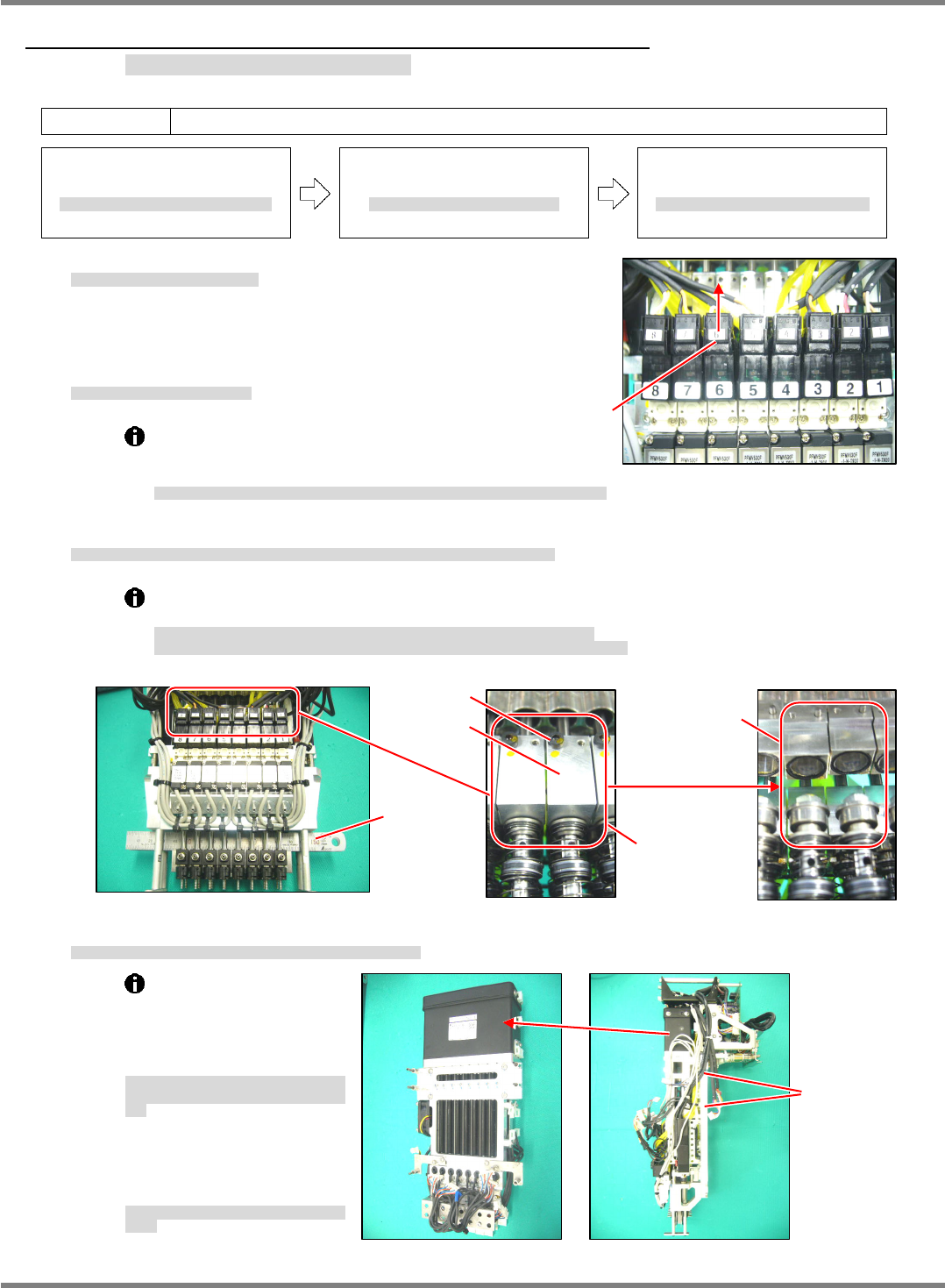
2. Disconnect the connector of the valve. (Fig. 1)
バルブのコネクタを抜きます。
(Fig. 1)
拔下阀的连接器。
(Fig. 1)
When disconnecting the connectors, be
careful not to break the wires. Do not pull the
cables.
コネクタを抜く時は、配線を切らないように注意してください。ケーブルを引っ張らないこと。
拔连接器时,请注意不要切断配线。不可拉拽电缆。
3. Insert a scale into the housing and separate the Z-axis linear motor from the ball spline. (Fig. 2)
ハウジング部にスケール等を挟み、
Z
軸リニアモータとボールスプラインの連結を分離します。
(Fig. 2)
在壳的部位夹入直尺等,使
Z
轴线性电机与滚珠花键的连结分离开来。
(Fig. 2)
The shafts of the Z-axis linear motor and ball spline are coupled with the plate.
Unseparated fitting part is can cause the shaft of the linear motor or ball spline to bend.
Z
軸リニアモータのシャフトとボールスプラインのシャフトはプレートで連結されています。
かみ合い部分を分離しないとリニアモータかボールスプラインのシャフトを曲げる原因になります。
Z
轴线性电机的轴与滚珠花键的轴是用板连结的。
如果不将咬合的部分分离,则可能使线性电机或者滚珠花键的轴弯曲。
4. Detach the Z-axis linear motor from the plate of the head unit. (Fig. 3)
ヘッドユニットのプレートから
Z
軸リニアモータを取り外します。
(Fig. 3)
从贴装头装置的板上将
Z
轴线性电机拆下。
(Fig. 3)
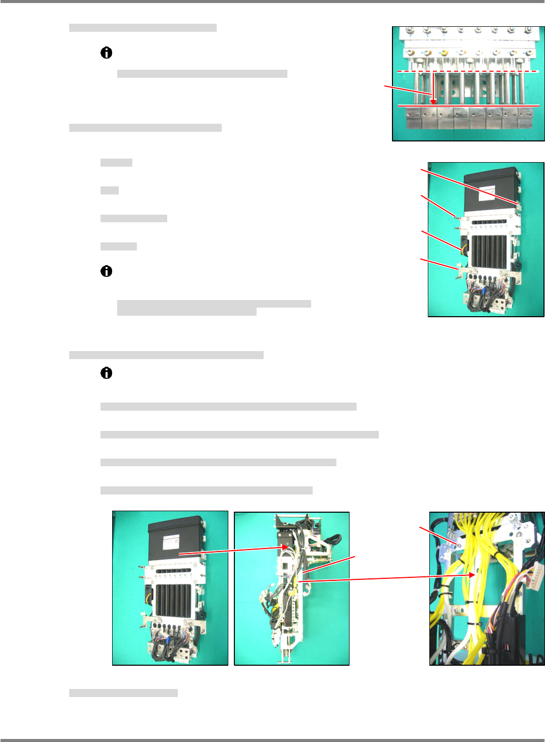
①
The Z-axis linear motor is
located by the positioning
pin (2-
5x10) and secured
with the bolt (4-M5x16).
Z
軸リニアモータは、規正ピン
(2-
5
10)
で位置
決めされ、ボルト
(4-M5 x 16)
で固定されていま
す。
Z
轴线性电机是由定位销
(2-
5
10)
定位、并用螺
栓
(4-M5 x 16)
固定的。
②
Cut the cable ties that
bundle the wires and tubes
as appropriate.
必要に応じて配線、配管の結束バンドを切断し
ます。
必要时可以切断配线、配管的绑扎带。
Fig. 3
4-M5 x 16
Fig. 2
Must be
separated
Scale
Fitting part
Plate
M2 x 6
NPM-D3
Service Manual
5.5 Light Weight 16-Nozzle Head
EJM6D3-MB-05SM-00(
編集中
).DOC Page 5-65
Fig. 4
Make sure to fall
smoothly.
5. Check the new Z-axis linear motor for proper sliding. (Fig. 4)
新しい
Z
軸リニアモータの摺動を確認します。
(Fig. 4)
确认新的
Z
轴线性电机的滑动情况。
(Fig. 4)
Make sure that all slide shafts slide
smoothly by their own weight.
すべてのスライドシャフトが、自重でスムーズに下降すること。
所有的滑动轴应能以自重滑顺地下降。
6. Fit the attached parts to the new linear motor.
(Fig. 5)
新しいリニアモータに付属部品を付け替えます。
(Fig. 5)
向新的线性电机换装上附属部件。
(Fig. 5)
①
Fan motor
FAN
モータ
风扇电机
②
Post
ポスト
柱
③
Bracket for securing wires
配線固定用のブラケット
固定配线的托架
④
Tie mount
タイマウント
带固定螺丝的绑扎带
The bolt and washer of the linear motor are made of
stainless steel.
Do not use the products made from iron.
リニアモータ部のボルト、ワッシャはステンレス製を使用しています。
鉄製のボルト、ワッシャは使用しないでください。
线性电机部分的螺栓、垫圈应使用不锈钢制的。
请不要使用铁制的螺栓、垫圈。
7. Attach the Z-axis linear motor to the plate of the head unit. (Fig. 6)
Z
軸リニアモータをヘッドユニットのプレートに取り付けます。
(Fig. 6)
将
Z
轴线性电机装到贴装头装置的板上。
(Fig. 6)
①
The Z-axis linear motor is located by the positioning pin (2-
5x10) and secured with the bolt
(4-M5x16).
Z
軸リニアモータは、規正ピン
(2-
5
10)
で位置決めされ、ボルト
(4-M5 x 16)
で固定されます。
Z
轴线性电机是由定位销
(2-
5
10)
定位、并用螺栓
(4-M5 x 16)
固定的。
②
Make sure that the shafts of the Z-axis linear motor and ball spline will not interfere with each other.
Z
軸リニアモータのシャフトとボールスプラインのシャフトを干渉させないように注意してください。
请注意不要让
Z
轴线性电机的轴与滚珠花键的轴相干涉。
③
Couple the shafts of the Z-axis linear motor and ball spline with the plate.
Z
軸リニアモータのシャフトとボールスプラインのシャフトをプレートで連結します。
用板连结
Z
轴线性电机的轴与滚珠花键的轴。
④
Use new cable ties to secure the wires and tubes where the old cable ties were cut.
切断した結束バンドの個所は、新しい結束バンドで配線、配管を固定します。
对切断了绑扎带的部位,用新的绑扎带将配线、配管固定住。
8. Reattach the Z-axis control board.
Z
軸コントロール基板を取り付けます。
装上
Z
轴控制基板。
‘5.5.1 Z-axis Control Board Detaching / Attaching’
Bracket
Fan moto
r
Tie mount
Pos
t
Fig. 5
4-M5 x 16
2-
5 x 10
Fig. 6
NPM-D3
Service Manual
5.5 Light Weight 16-Nozzle Head
Page 5-66 EJM6D3-MB-05SM-00(
編集中
).DOC
5.5.7 Secondary Filter Replacement
2
次フィルタ交換
2
次过滤器的更换
Unit No.
N610096433AA
5.1.1 Head Unit Detaching and
Attaching
ヘッドユニット取り外し
/
取り付け
头装置的拆卸和安装
5.5.7 Secondary Filter
Replacement
2
次フィルタ交換
2
次过滤器的更换
5.1.1 Head Unit Detaching and
Attaching
ヘッドユニット取り外し
/
取り付け
头装置的拆卸和安装
28.
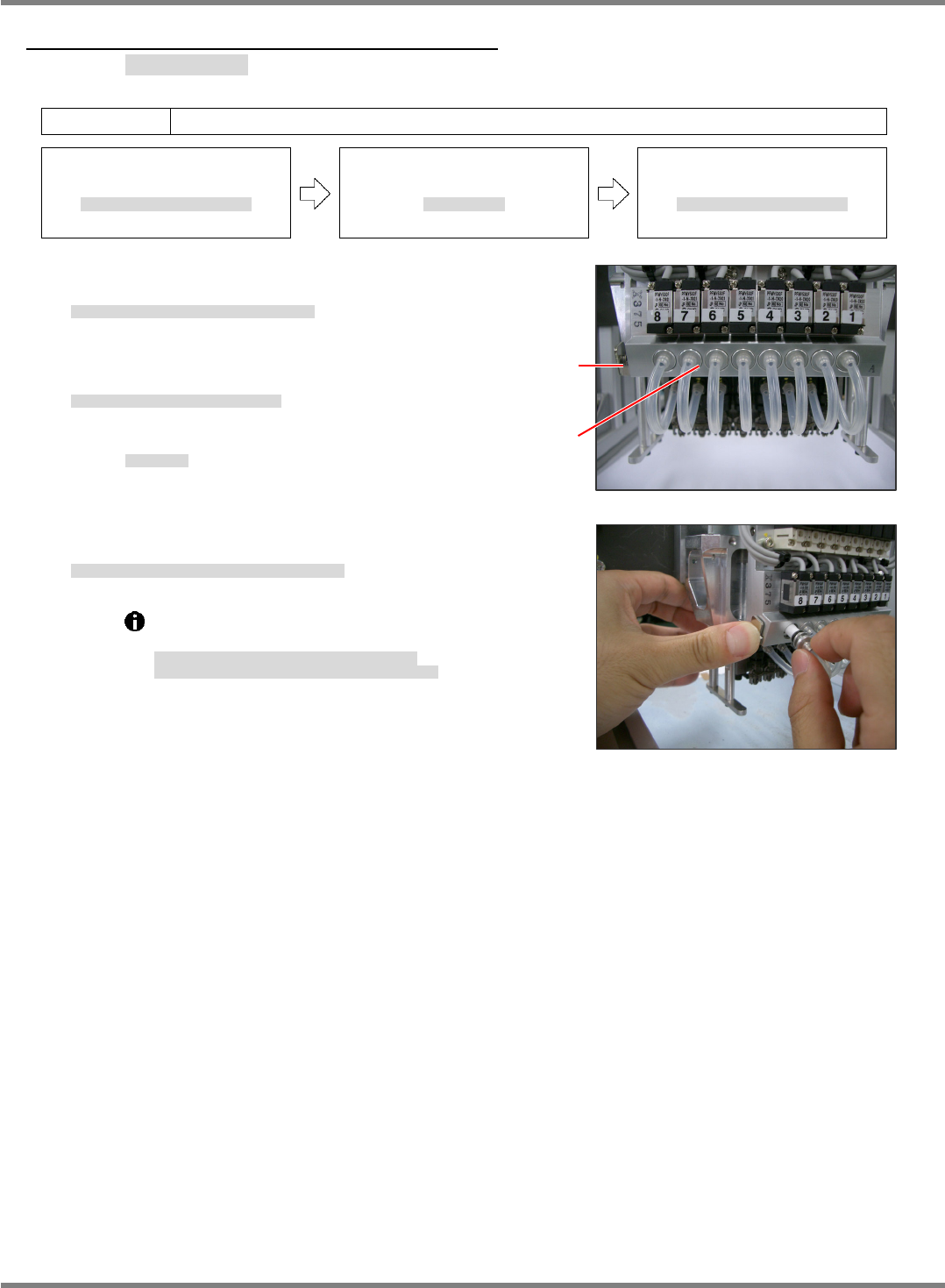
1. Press the button shown in the right photo and remove
the holders. (Fig. 2)
取り外しボタンを押してホルダを引き抜く。
(Fig. 2)
按下拆卸按钮、拔出支架。
(Fig. 2)
2. Replace the filters from the removed holders.
取り出したホルダからフィルタを交換する。
对拆下的支架更换过滤器。
Filter No.:
N510054846AA
フィルタ品番
过滤器的部件编号
3. After replacing, set the holders back into place while holding down
the button.
交換後、取り外しボタンを押しながらホルダを元に戻す。
更换后,一边按下拆卸按钮一边将支架装回原处。
Detach the head before replacing the filters.
Do not pull the air hose when pulling the holders.
フィルタ交換時はヘッドを取り外して行ってください。
ホルダを引き抜く時は、エアーホースを引っ張らないこと。
要更换过滤器时,请将贴装头卸下后实施。
拔下支架时,不可拉拽气管。
Fig. 2
Fig. 1
Removal
button
Holde
r
(Filter)