NPM-D3维修手册.pdf - 第166页
NPM-D3 Service Manual 5.4 2-nozzle Head Page 5-38 EJM6D3-MB-05SM-00( 編集中 ).DOC Nozzle Shaft Assembly and Attaching 組立て / 取り付け 组装 / 安装 16. 1. Replace the ball spline. ボールスプラインを交換します。 交换滚珠花键。 2. Attach the piston and mea…
NPM-D3
Service Manual
5.4 2-nozzle Head
EJM6D3-MB-05SM-00(
編集中
).DOC Page 5-37
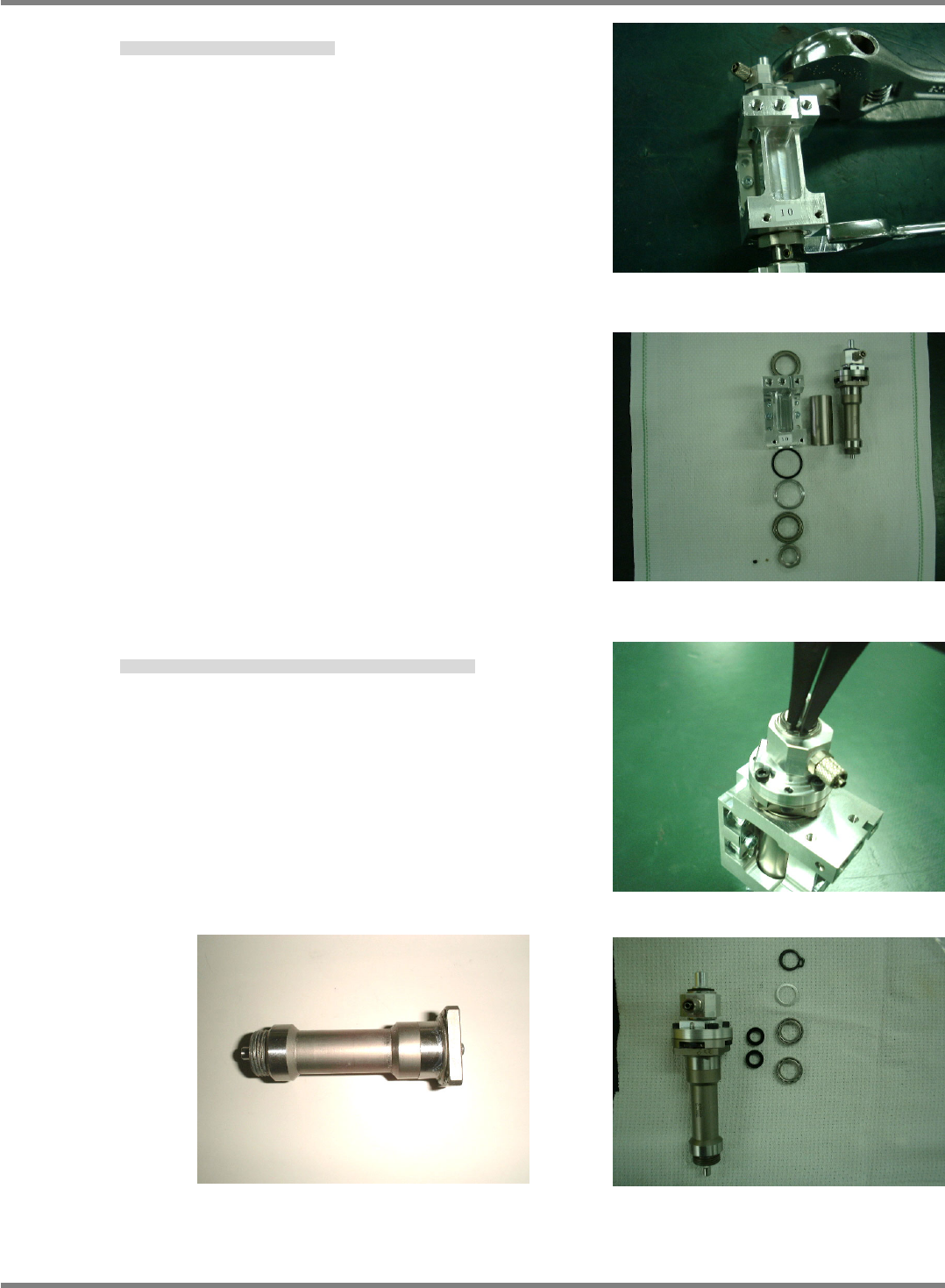
6. Disassemble the nozzle unit. (Figs. 4 and 5)
ノズルユニットを分離します。(Figs. 4 and 5)
将吸嘴装置拆卸。(Figs. 4 and 5)
7. Detach the upper snap ring and ball spline. (Figs. 6 and 7)
上部スナップリングを外し / ボールスプラインを外します。(Figs. 6 and 7)
卸下上部开口环后,卸下滚珠花键。(Figs. 6 and 7)
Fig. 4
Fig. 5
Fig. 6
Fig. 7
Ball spline is single piece and cannot be disassembled
NPM-D3
Service Manual
5.4 2-nozzle Head
Page 5-38 EJM6D3-MB-05SM-00(
編集中
).DOC
Nozzle Shaft Assembly and Attaching
組立て / 取り付け
组装 / 安装
16.
1. Replace the ball spline.
ボールスプラインを交換します。
交换滚珠花键。
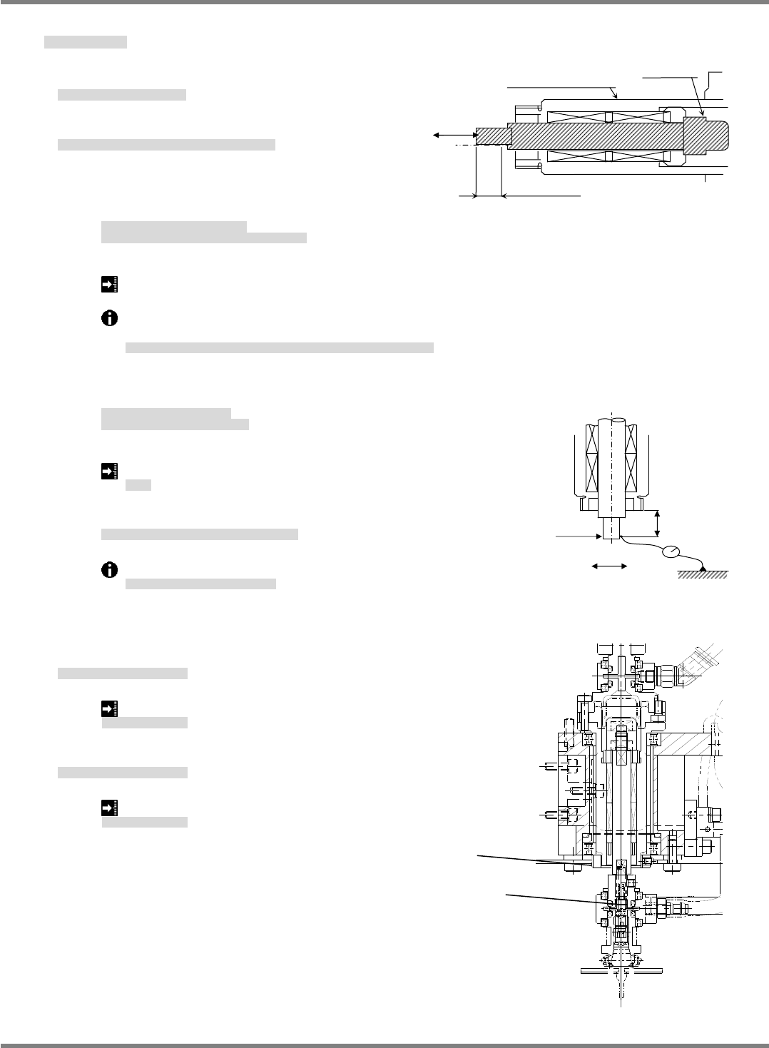
2. Attach the piston and measure the ball spline. (Fig. 1)
ピストンの取り付け / ボールスプラインの測定。(Fig. 1)
活塞的安装 / 滚珠花键的测量。(Fig. 1)
①
Measure ball spline sliding.
Measure with a push-pull gauge in the sliding
resistance range of 8 mm.
ボールスプライン摺動を測定します。
摺動抵抗 8 mm の範囲でプッシュプルゲージにて測定
测量滚珠花键的往返移动值。
在往返移动抵抗 8mm 的范围内,用推拉规测量。
P =
0.30 N
Set the ball spline in the horizontal posture as shown above and measure sliding in both
directions.
ボールスプラインは、上図のように水平に設置し、行き戻りの摺動を測定する。
按照上图,将滚珠花键设置水平,测量往返移动值。
②
Measure the amount of play after assembly. (Fig. 2)
Push-pull gauge / Dial gauge
組付け後のガタ量を測定。(Fig. 2)
プッシュプルゲージ / ダイヤルゲージ
测量组装后的游隙量。(Fig. 2)
推拉规 / 千分表
Play space :
2
m
ガタ量
游隙量
③
Measure in the separated state with load applied as shown below.
下記のように一旦荷重をかけて離した状態で測定。
如下所示,在暂时施加压力后将其放开的状态下进行测量。
Measure the maximum play 4 times at every 90
.
90
ごとに
4
か所測定し、最大のガタ量
在每
90
的位置上测量
4
处,最大的游隙量值。
3. Assemble the nozzle unit. (Fig. 3)
ノズルユニットの組立て。(Fig. 3)
组装吸嘴装置。(Fig. 3)
Nut tightening torque: 8
0.8 N
ナットの締付けトルク
螺母的拧紧扭矩
4. Assemble the shaft tip. (Fig. 3)
シャフト先端部を組立て。(Fig. 3)
组装轴的端部。(Fig. 3)
Bolt tightening torque: 0.4
0.04 N
ボルトの締付けトルク
螺栓的拧紧扭矩
8 mm
(Measurement range)
P
Ball spline
Piston
Piston tightening torque
=SPECIFICATION=
3.5
0.35 N
Fig. 1
12
0.4N
Play
Fig. 2
Fig. 3
Nut
Bolt
NPM-D3
Service Manual
5.4 2-nozzle Head
EJM6D3-MB-05SM-00(
編集中
).DOC Page 5-39
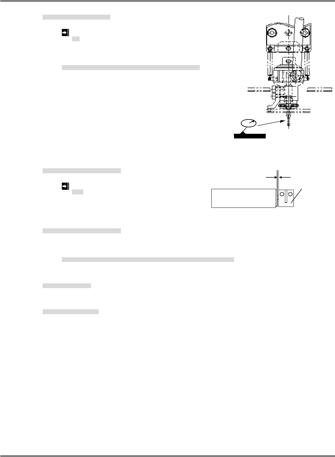
5. Measure the nozzle holder rotational runout. (Fig. 4)
ノズルホルダーの回転振れ測定。(Fig. 4)
测量吸嘴支架的转动振动。(Fig. 4)
Runout:
0.10 mm
振れ
振动
After assembling the head, measure the rotational runout
of the nozzle holder with a lever-operated dial gauge.
ヘッド組立て後、ノズルホルダーの回転振れ量をダイヤルゲージにて測定します。
组装吸头后,用扛杆式千分表测量吸嘴支架的转动振动量。
6. Attach the coupling to the motor and lock in place.
モータにカップリングを取り付け、固定します
在电机上安装联轴器后,将其固定住。
Clearance: 0.4 ~ 0.6 mm
すき間
间隙
7. Attach the motor and tighten the coupling.
モータを取り付け、カップリングを締めます。
安装电机后,拧紧联轴器。
Turn the holder to the
origin position (nozzle guide comes to right when viewed from front) and
tighten the coupling.
ホルダを
原点位置
(
正面からみて右側にノズルガイドがくる位置
)
に回してカップリングを締めます。
将支架转动到
原点位置
(
从正面看,右侧有吸嘴导轨的位置
)
后,拧紧联轴器。
8. Attach the top cover.
上面カバーを取り付けます。
安装上面盖。
9. Attach the head unit.
ヘッドユニットを取り付けます。
安装头装置。
‘Head Unit Replacement Procedure’.
Fig. 4
0.4 ~ 0.6 mm
Motor
Coupling