MDO3000 Programmer Manual.pdf - 第133页
Command Groups In this case, th e Digital Collection data returned will be 32-bit packed integers, where each p oint is represented as follows. Note that the trigger state bit described below is only a vailable when ACQu…

Command Groups
X
1
= -500ms + 1ms
*(1-1)
= -500ms
X
2
= -500ms + 1ms * (2 - 1)
= -499ms
.. .
X
1000
= -500ms + 1ms * (1000 - 1) = 499ms
Vertical (amplitude) values:
Y
i
=YZEro+(YMUlt*DataPoint
i
)
= 0.0V + (0.004 * DataPoint
i
)
YZERO is in vertical units; in this example, 0.0 Volts.
YMULT is in vertical units per digitizing level (DL), in this example,
0.004 Volts per digitizing level.
From
CURVe query:
DataPoint
1
=-10
DataPoint
2
=-11
DataPoint
1000
=23
Y
1
= 0.0V + (0.004V/DL * -10DL) = –0.040V
Y
2
= 0.0V + (0.004V/DL * -11DL) = –0.044V
Y
1000
= 0.0V + (0.004V/DL * 23DL) = 0.092V
Further Explanation of the
Digital Collection
When the waveform source is set to DIGital using the DATa:SOUrce command, a
WFMOutpre? and CURVe? query (or a WAVFRM? query) will return the Digital
Collection data. The format and content of this data will depend upon the width
that has been specified using the
DATa:WIDth command, which can be either
4 or 8 bytes per point.
NOTE. Applies to MSO/MDO4000/B models only as well as MDO3000 and
MDO4000C models with option MDO3MSO or MDO4MSO installed.
4 Byte Data. When the data width is set to 4 bytes (using either DATa:WIDth or
WFMOutpre:BYT_Nr, the Digital Collection represents
the states of digital channe
ls D0 – D15,
the digital representations of analog Channels 1 – 4, and
the trigger state.
2-102 MDO4000/B/C, MSO/DPO4000B and MDO3000 Series Oscilloscopes Programmer Manual
Command Groups
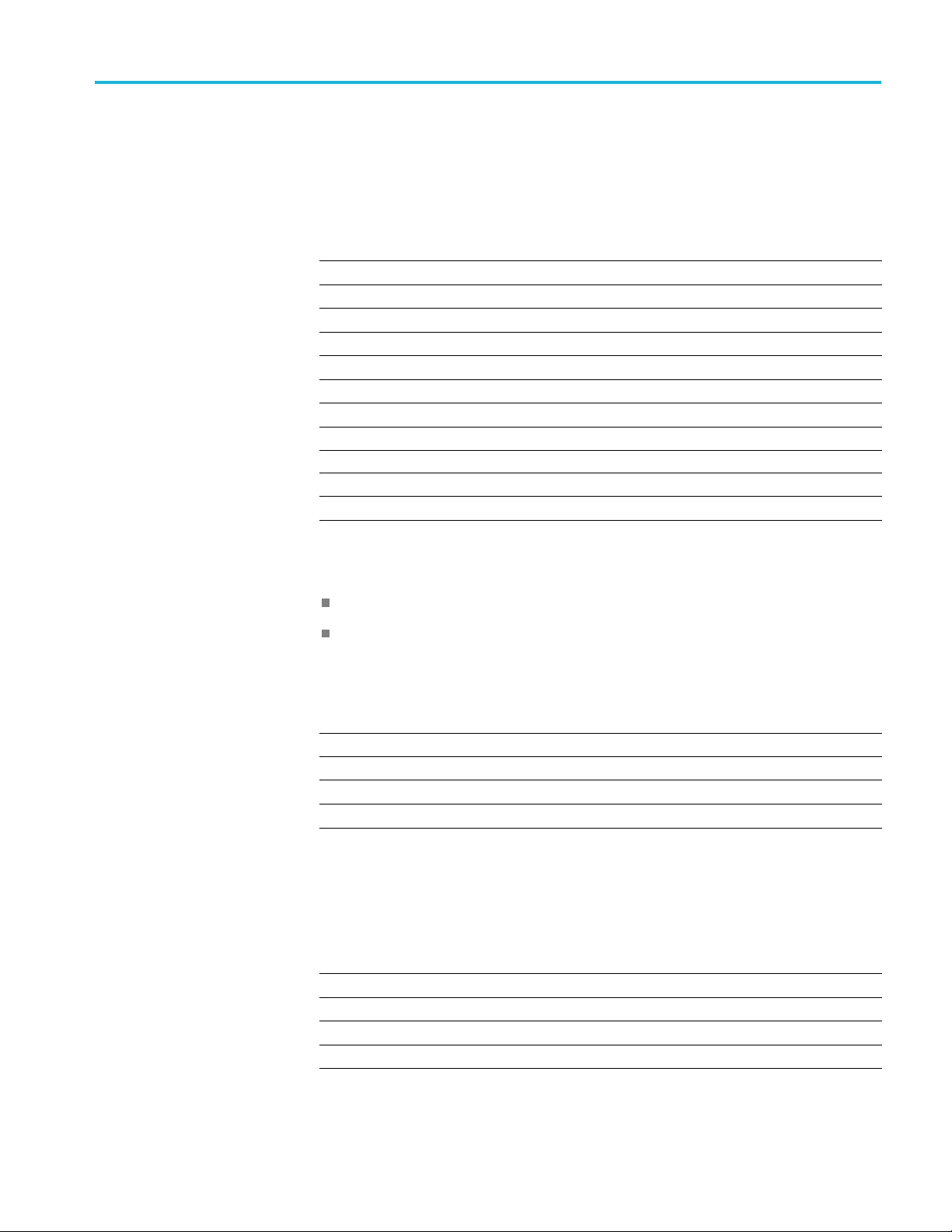
In this case, th
e Digital Collection data returned will be 32-bit packed integers,
where each point is represented as follows. Note that the trigger state bit described
below is only available when ACQuire:MAGnivu is 1 (on).
Table 2-46: Digital Collection: 4 Byte Data
Bit number Description
31– 22 not used
21 trigger state
20
not used (always 1)
19
CH4 digital state
18
CH3 digital state
17
CH2 digital state
16
CH1 digital state
15 D15 state
...
1 D1 state
0 D0 state
8ByteData. When the data width is set to 8 bytes, the Digital Collection
represents
the transition state information for digital channels D0 – D15 and
the digital representations of analog Channels 1 – 4.
The "transition state" refers to MSB and LSB bits which together represent the
state of the digital channel during the sampling period, as fol
lows:
MSB LSB Transition/State
0 0 Low
01High
10
Single transition
1 1 Multiple transitions
If the width specified using the DATa:WIDth command is 8 bytes, the Digital
Collection data returned will be 64-bit packed integers, where each point is
represented as follows:
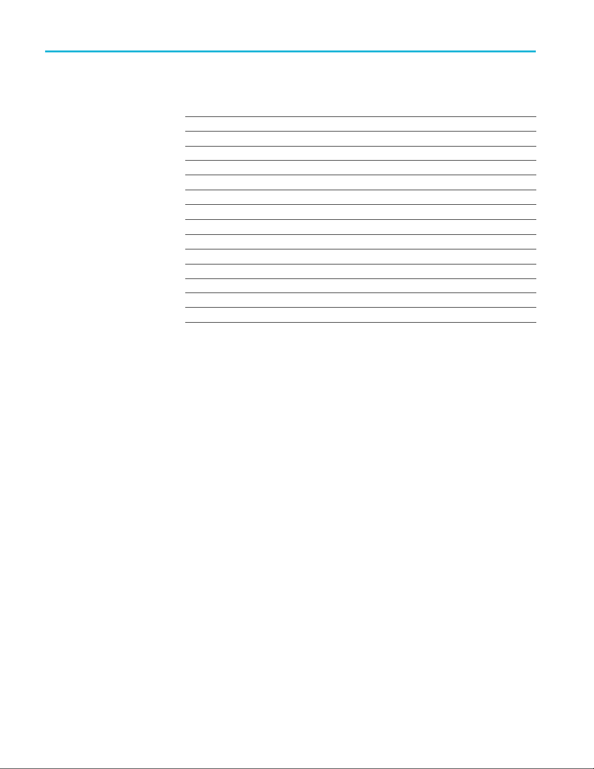
Table 2-47: Digital Collection: 8 Byte Data
Bit Number Description
63 — 52 not used
51
CH4 trans ition state MS B
50
CH3 trans ition state MS B
49
CH2 trans ition state MS B
MDO4000/B/C, MSO/DPO4000B and MDO3000 Series Oscilloscopes Programmer Manual 2-103
Command Groups
Table 2-47: Digital Collection: 8 Byte Data (cont.)
Bit Number Description
48
CH1 transition state M SB
47
D15transitionstateMSB
...
33
D1 transition state MSB
32
D0 transition state MSB
31 — 20 not used
19
CH4 transition state LSB
18
CH3 transition state LSB
17
CH2 transition state LSB
16
CH1 transition state LSB
15
D15 transition state LS B
...
1
D1 transition state LSB
0
D0 transition state LSB
For example, to find the transition state of the digital channel D0, set
DATa:SOUrce to
DIGITAL and DATa:WIDth to 8. Look at bits 0 and 32 in the
d
ata returned by the
CURVe? or WAVFrm? queries, where bit 0 is the transition
state LSB and bit 32 is the transition state MSB for D0.
2-104 MDO4000/B/C, MSO/DPO4000B and MDO3000 Series Oscilloscopes Programmer Manual