SIPLACE D4-D4i 工程师手册_EN.pdf - 第118页
Service Work PCB conveyor system 4.4.4 Repla cing the Toothed Belt of the Driv e Unit [00355553] 118 Service Manual SIPLACE D4/D4i Removal ► Switch off the machine and secure it to prevent unau - thorized rea ctivation. …
Service Work
4.4.4 Replacing the Toothed Belt of the Drive Unit [00355553] PCB conveyor system
Service Manual SIPLACE D4/D4i 117
Installation
4.4.4
4.4.4 Replacing the Toothed Belt of the Drive Unit [00355553]
Replacing the Toothed Belt of the Drive Unit [00355553]
Overview
CAUTION! Do not damage the toothed belt!
The toothed belts must not be stretched or kinked!
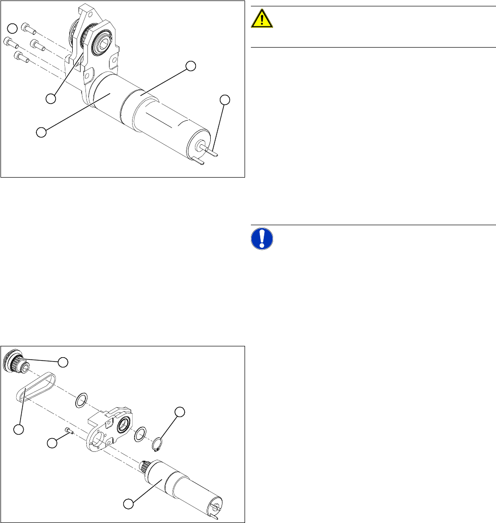
► Fit the new DC geared motor (5) by following the
above instructions in reverse order.
The entire width of the toothed belt (3) must engage
at the top and bottom toothed disks.
► Fix the DC geared motor (5) with the 4 M3 hexagonal
socket-head screws (2).
► Tension the toothed belt (3) by moving the DC geared
motor in the fastening holes. The belt tension must be
between
10 and 15 N.
► Reconnect to the electrical system (1) and secure the
connection cable with a heat-shrinkable hose (4).
NOTICE! After the geared motor has been in-
stalled, you must make certain that the direction of rota-
tion and the conveyor speed (motor voltage) are correct.
5
1
4
3
2
Legend
1. DC geared motor
2. Circlip
3. 4 x fastening screws
4. Toothed belt
5. Toothed disk
The DC geared motors, including the motor mounts of all
5 conveyor areas, are of like construction. Please bear in
mind the following differences during assembly and dis-
assembly:
▪ The motor mount is installed at an angle (tilted), ac-
cording to the requirements of the installation site.
1
5
4
3
2
Service Work
PCB conveyor system 4.4.4 Replacing the Toothed Belt of the Drive Unit [00355553]
118 Service Manual SIPLACE D4/D4i
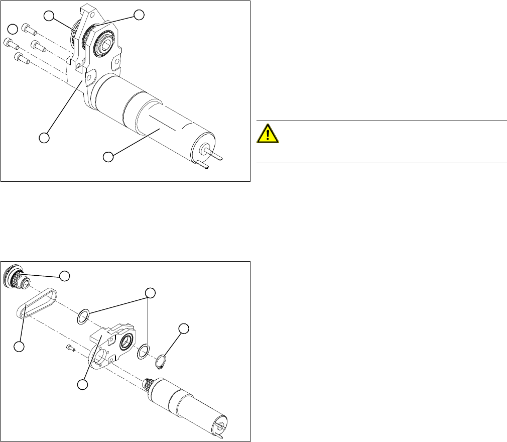
Removal
► Switch off the machine and secure it to prevent unau-
thorized reactivation.
► Remove the complete drive unit (5).
► From the outer side of the conveyor, undo the fixtures
holding (2) the DC geared motor (1).
► Tilt the DC geared motor (1) with its toothed disk (4)
a little, so that the small toothed belt comes free of the
toothed disk.
CAUTION! Do not damage the toothed belt!
The toothed belts must not be stretched or kinked!
► Pull the DC geared motor out.
► Please note:
⇨ The toothed disk on the motor shaft must be
moved out in such a manner that it does not get
caught in the toothed belt.
► Remove the circlip (1) and the shims/washers (2).
► Use a small rubber mallet to carefully knock the
toothed disk (3) out of the motor mount (5).
► Remove the toothed belt (4) from the mount.
5
1
4
3
2
1
5
4
3
2
Service Work
4.4.5 Replacing the Conveyor Toothed Belt [00359917-xx] PCB conveyor system
Service Manual SIPLACE D4/D4i 119
4.4.5
4.4.5 Replacing the Conveyor Toothed Belt [00359917-xx]
Replacing the Conveyor Toothed Belt [00359917-xx]
Parts
▪ Synchroflex toothed belt 1315 long for input and output conveyor [00359917-xx]
▪ Synchroflex toothed belt 1160 long for placement areas 1 and 2 [00364847-xx]
▪ Synchroflex toothed belt 990 long for intermediate conveyor [00356851-xx]
Overview
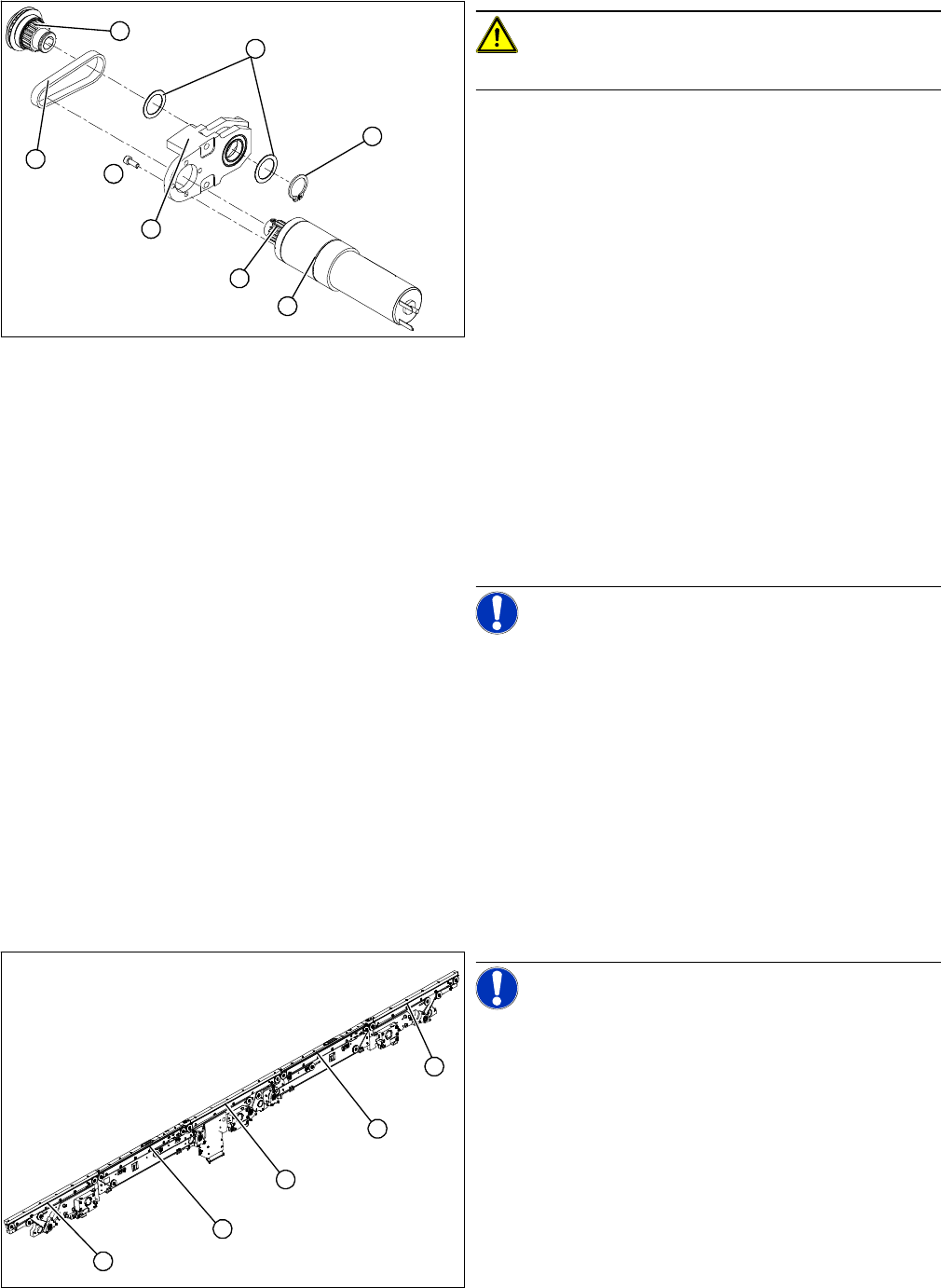
CAUTION! Do not damage the toothed belt!
The toothed belts must not be stretched or kinked!
► Insert the new toothed belt (1) into the motor mount
(2) and place the belt around the toothed disk (3) of
the geared motor.
► Place the toothed belt around the toothed disk (4) of
the conveyor toothed belt and insert the toothed disk
in its mount.
► Use a rubber mallet to carefully knock the toothed
disk into position.
► Install the shim/washer (7) and the circlip (8).
► Loosely fasten the DC geared motor (5) with the 4 M3
hexagonal socket-head screws (6). The entire width
of the toothed belt must engage at the top and bottom
toothed disks.
► Tension the toothed belt (1) by moving the DC geared
motor in the fastening holes. The belt tension must be
between
10 and 15 N.
► Fit the complete motor unit.
NOTICE! After the drive unit has been installed,
you must make certain that the direction of rotation and
the conveyor speed (motor voltage) are correct.
6
8
7
1
5
4
3
2
NOTICE! The following diagrams apply to the
standard conveyor system (fixed side - right). Depending
on the conveyor side (left or right), either the hexagon
shaft guided block or the DC geared motor will be fitted.
Legend
1. Input conveyor
2. Placement area 1
3. Intermediate belt
4. Placement area 2
5. Output conveyor
1
5
4
3
2