SIPLACE D4-D4i 工程师手册_EN.pdf - 第77页
Service Work 4.3.1 Changeover Table Component Handling Service Manual SIPLACE D4/D4i 77 See also 4.3.1.1 Safety Instru ctions [ ➙ 75] Replacing th e fixed and guide cas tors (D4 sho wn as ex - ample) Legend 1. Lay th…

Service Work
Component Handling 4.3.1 Changeover Table
76 Service Manual SIPLACE D4/D4i
4.3.1.2
4.3.1.2 Preparations for Service Work
Preparations for Service Work
► Move the relevant changeover table out of the machine. (See operating manual)
► When replacing the bellows cylinder:
Take the feeder modules from the changeover table and place them on a clean surface. In this case,
the tape reels can remain in the container.
► When exchanging the guide castors and fixed castors:
Same steps as above for exchanging the bellows cylinder.
In addition, remove all of the tape reels from the container and put them down in order.
► When replacing the cable for the changeover table and/or the communications unit:
You do not need to dismantle the feeder modules.
Tools and Equipment
▪ Set of Allen wrenches
▪ Diagonal cutter (for cable tie)
▪ External power supply for changeover table
▪ Extension lead for changeover table
4.3.1.3
4.3.1.3 Replacing the Fixed and/or Guide Castors
Replacing the Fixed and/or Guide Castors
Parts
▪ 2x fixed castor [03044881-xx]
▪ 2x double guide castor [03050704-xx]
Removal/Installation
The changeover table is dismantled and prepared, as described in "4.3.1.2 Preparations for Service
Work" [ ➙ 76].
► Tear down the changeover table and remove the partition plates in the tape container.
► Enlist the aid of a 2nd strong person and place the changeover table on its side (1).
► Undo the screws fastening the fixed castor and/or guide castor to be exchanged (size 6 Allen
wrench: ).
► Insert the new guide castors and/or fixed castors and fix these back into place with 4 hexagon sock-
et-head screws each.
► With the aid of a 2nd strong person, set the changeover table back up.
Secure the changeover table to prevent it from rolling away by itself.
► If you have no further parts to be replaced, perform the appropriate "Final Steps" (see "4.3.1.6 Final
Steps" [ ➙ 79]).
CAUTION
Take care when lowering or raising the handle of the changeover table. There is a risk of minor
injuries from the handle, such as pinching or scraping.
► For this reason, always hold the handle with both hands.
WARNING
The changeover table needs to be laid on its side to remove the fixed castor and/or guide cas-
tor.
Two people are required for this as the changeover table is very heavy.
Service Work
4.3.1 Changeover Table Component Handling
Service Manual SIPLACE D4/D4i 77
See also
4.3.1.1 Safety Instructions [ ➙ 75]
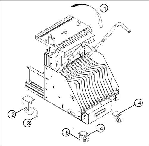
Replacing the fixed and guide castors (D4 shown as ex
-
ample)
Legend
1. Lay the changeover table on its side (2nd person re-
quired) before removing the rollers.
2. Fixed castors (2 units)
3. 8 hexagon socket-head screws M8 x 16
4. Double guide castors (2 units)
5. 8 hexagon socket-head screws M8 x 16
Service Work
Component Handling 4.3.1 Changeover Table
78 Service Manual SIPLACE D4/D4i
4.3.1.4
4.3.1.4 Replacing the Communication Unit (Feeder Control Unit) [03002179-xx]
Replacing the Communication Unit (Feeder Control Unit) [03002179-xx]
See also
4.3.1.6 Final Steps [ ➙ 79]
4.3.1.5
4.3.1.5 Replacing the Changeover Table Connection Cable
Replacing the Changeover Table Connection Cable
Power supply cable "changeover table"
► Perform the "Preparatory Steps". (See "4.3.1.2 Preparations for Service Work" [ ➙ 76].)
You do not need to dismantle the feeder modules.
► Unplug plugs X13 and X15 of the communication unit cable.
► Disconnect the pneumatic hose.
► Disconnect the ground cable at the connection provided.
► The ground cable is looped through the changeover table and fastened at several connections.
To avoid weaving out the complete ground cable, disconnect the cable at the cable shoe.
► Open the cord grip and remove the entire cable.
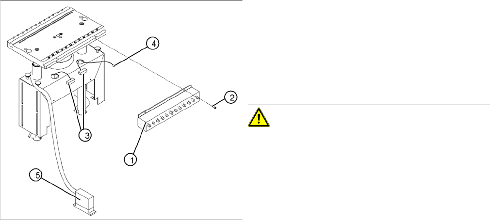
Replacing the communications unit; view of the change
-
over table connection area (D4 shown as example)
Legend
1. Communication unit (Feeder Control Unit)
2. Fasteners for the communications unit: 2 M 4 x 6 hex-
agon socket-head screws
3. "Changeover table" connection cable
4. Ground cable with cable shoe
5. "Changeover table" connection cable - connector
CAUTION! The same fastening screws can be
used to fit a splice detection unit. Bear this in mind when
loosening the screws.
► Perform the "Preparatory Steps" (see "4.3.1.2 Prepa-
rations for Service Work" [ ➙ 76]).
You do not need to dismantle the feeder modules.
► Unplug the two press-fit connections for the "change-
over table“ cable, at the back of the communication
unit housing (3) and remove the ground cable (4).
► Hold the communication unit and undo the fastening
screws (2).
► Remove the communication unit (1).
► Place the new communications unit on the retaining
brackets and tighten the screws to fasten it.
► Reconnect the "changeover table" cable at the back
of the communications unit housing.
► If you have no further parts to be exchanged, perform
the appropriate "Final Steps", including a table func-
tion check with SITEST.