SIPLACE D4-D4i 工程师手册_EN.pdf - 第82页
Service Work Component Handling 4.3.2 Cutter 82 Service Manual SIPLACE D4/D4i 4.3.2.4 4 . 3 . 2 . 4 O v e r v ie w o f C u t t e r Overview of Cutter Overview: Removing and Installing the Cover Plate and the Tape Deflect…
Service Work
4.3.2 Cutter Component Handling
Service Manual SIPLACE D4/D4i 81
▪ Mounting plate [00312731-01]
▪ 2 large parallel clamps (or mounting plate, see above)
▪ Flat, sturdy work bench to fasten the removed cutter (or mounting plate, see above)
▪ Loctite No. 234 [00334892-01]
▪ Molykote paste 250 g [02100335-01] (recommended) or ISOFLEX TOPAS NCA 52 tube 50g
[00330850-01]
▪ Water-insoluble, fine-tip marker and
▪ a dry and clean cloth
▪ Current SIPLACE D4 spare parts catalogue and SIPLACE D4 circuit diagrams
▪ SITEST program and current SITEST operating manual
See also
5 Measuring Equipment and Tools [ ➙ 189]
Service Work
Component Handling 4.3.2 Cutter
82 Service Manual SIPLACE D4/D4i
4.3.2.4
4.3.2.4 Overview of Cutter
Overview of Cutter
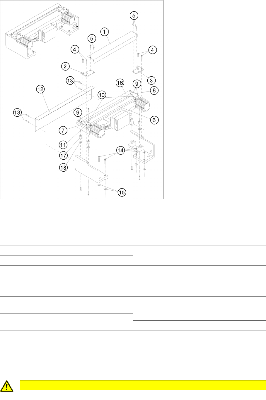
Overview: Removing and Installing the Cover Plate and the Tape Deflector
Legend
1 Cover plate 10 Screws to fasten the tape deflector: 1 coun-
tersunk screw each -> do not loosen!
2 Cover plate holder, left 11 Holddowns (at left and right) with spacers
inserted underneath them
3 Cover plate holder, right
4 Screws to fasten the cover plate holder:
2 hexagon socket head screws M4 x 8 DIN
84 or 2 countersunk screws R M4 x 6 DIN
965 each
12 Deflector plate
13 Screws to fasten the deflector plate: 4
socket hex head cap screws M4 x 8
5 Screws to fasten the cover plate (incl. tape
deflector) -> do not loosen!
14 Screws to fasten the cutter on the machine
base
4 socket hex head cap screws M 6 x 25 *)
6 Tape deflector (with moveable blade un-
derneath) 15 Any disks or plates installed underneath
7 Tape deflector holder, left 16 Stationary blade
8 Tape deflector holder, right 17 Rubber-metal vibration damper
9 Screws to fasten the tape deflector holders:
2 socket hex head cap screws M4 x 35
each on the left and right
18 Any disks and spring washers installed un-
derneath
CAUTION
Tighten the screws to the correct torque.
Service Work
4.3.2 Cutter Component Handling
Service Manual SIPLACE D4/D4i 83
*) Loosen these screws only when removing/installing the cutter.
See also
6.4.3 Check the gap between the empty-tape baffle, inside and the leading edge of the tape deflec-
tor. [ ➙ 223]
4.3.2.14 Final Steps [ ➙ 107]
Tightening Torques for Cutter Screws
4.3.2.5
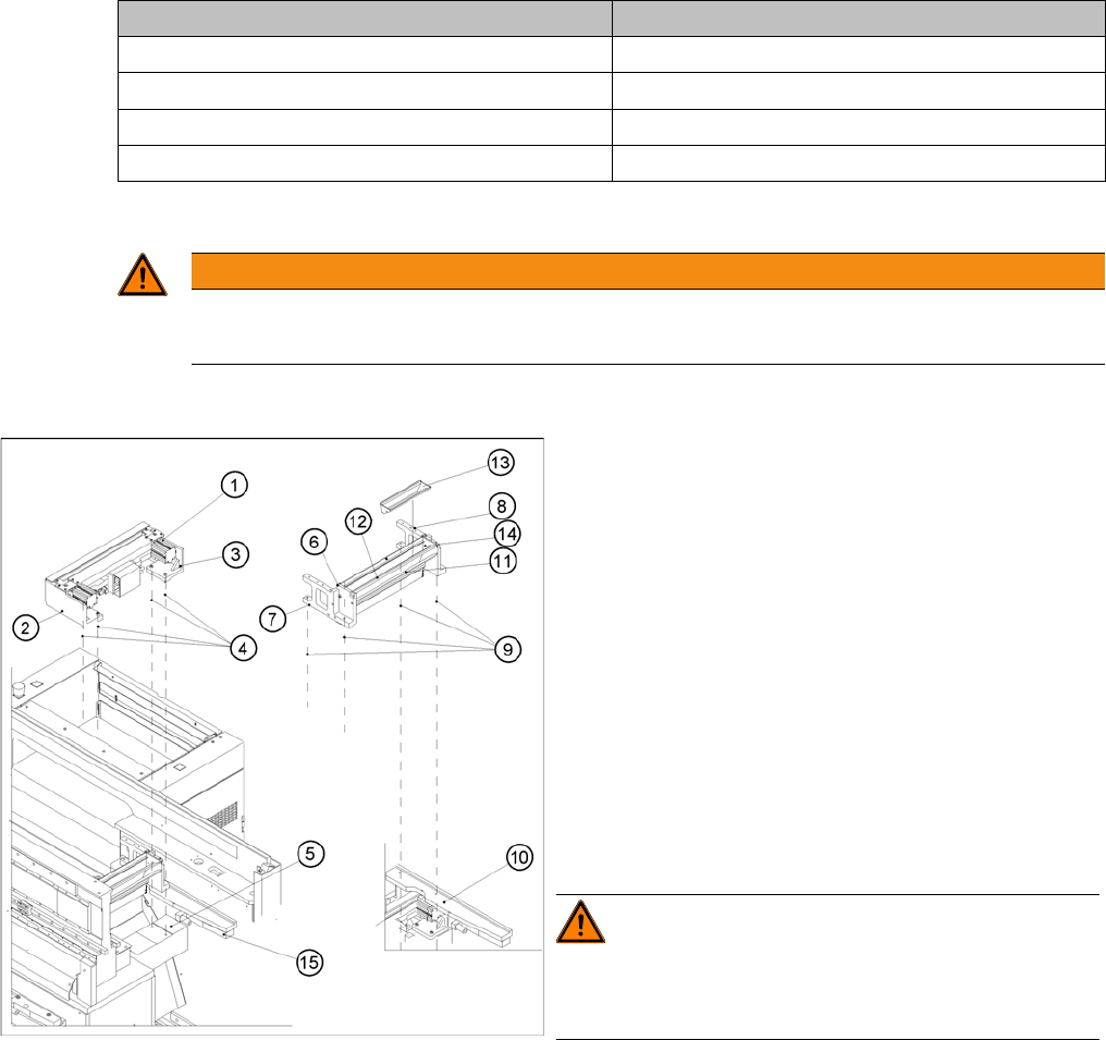
4.3.2.5 Exchanging the Pneumatic Cutter
Exchanging the Pneumatic Cutter
Removing the Cutter
Thread Tightening torque (Nm)
M3 1.0 – 1.3
M4 2.7 – 3.0
M5 5.5 – 6.0
M6 9.5 – 10.2
WARNING
► Wear thick protective gloves
► When removing the cutter, hold it only on the left and right, on the outside.
► Turn the machine and then the flow of compressed
air ON.
► Disconnect the movable changeover table from the
machine and move it out of the machine.
► Switch off the supply of compressed air at the com-
pressed air unit and actuate the needle valve on the
compressed air unit to bleed the compressed air
lines.
► Turn the machine OFF, disconnect the machine from
the line and turn off the flow of compressed air at the
compressed air unit.
► Loosen the screws fastening the empty-tape duct as-
sembly (6) (M6x35), lift the empty-tape duct and
place it carefully down on the PCB conveyor. The
nozzle changer remains fixed to the empty-tape duct.
WARNING! There is always a risk of injuring
yourself on the cutting edge of the blades.
For this reason, the deflector plate, the cover and the pro-
tective sheet must be left in place.
► Undo the fixtures for the stop buffer assembly (15)
(two hexagon-socket head screws M8x25 on each
side) on the left and right-hand sides of the machine
base, under the surface supporting the changeover
table.