SIPLACE D4-D4i 工程师手册_EN.pdf - 第203页
Settings 6.2.3 Description of the PCB boards on the Gantry Gantry Service Manual SIPLACE D4/D4i 203 Description of LEDs on t he Gantry Head Distributor SM = stepping motor Legend PCB labeling LEDS for oeprating states De…
Settings
Gantry 6.2.3 Description of the PCB boards on the Gantry
202 Service Manual SIPLACE D4/D4i
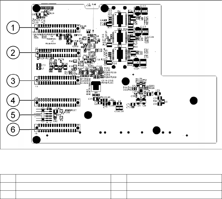
Gantry head distributor (from below)
Legend
See also
6.3.2.1 8-fold DIP Switch of the gantry head distributor (incl. switch S1) – C&P6/12 [ ➙ 207]
6.2.4.1 DIP Switch on Gantry Head Distributor [ ➙ 205]
1 X1 flat ribbon cable 4 X4 not connected
2 X2 flat ribbon cable 5 X15 connector for X-axis track signals
3 X3 flat ribbon cable 6 X9 flat ribbon cable
Settings
6.2.3 Description of the PCB boards on the Gantry Gantry
Service Manual SIPLACE D4/D4i 203
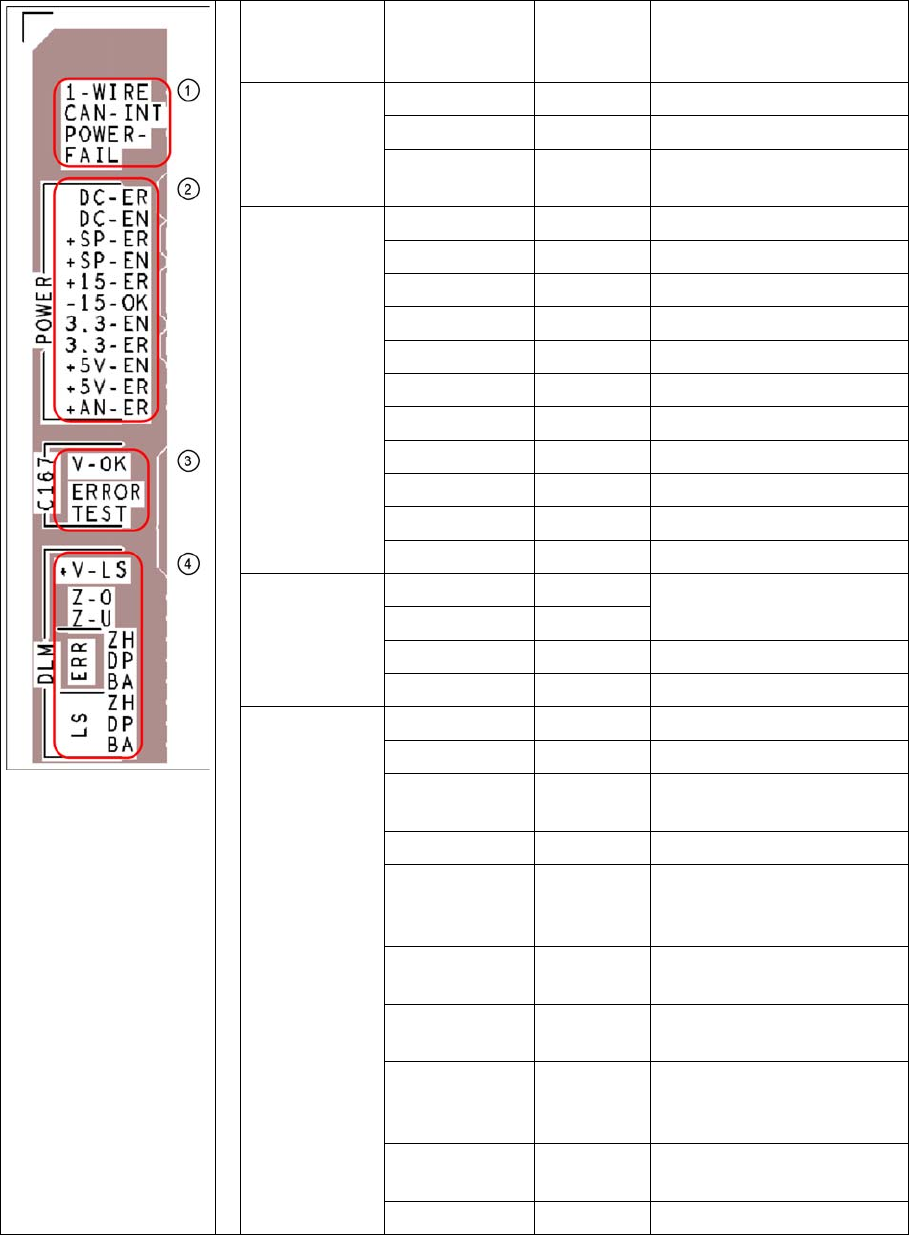
Description of LEDs on the Gantry Head Distributor
SM = stepping motor
Legend PCB labeling LEDS for
oeprating
states
Description
1
CAN Bus
1-WIRE Not in use
CAN-INT OFF not used
POWER-FAIL OFF Error +24 V power supply
(from the main machine)
2
Status voltage
supplies
DC-ER OFF Error DC/DC converter
DC-EN ON Enable DC/DC converter
+SP-ER OFF Error +5V track encoder
+SP-EN ON Enable +5V track encoder
+15-ER OFF Error +15V
-15-OK ON -15V is OK
3.3-EN ON Enable +3.3V digital
3.3-ER OFF Error +3.3V digital
+5V-EN ON Enable +5 V digital
+5V-ER OFF Error +5V digital
+AN-ER OFF Error analog supply C167
3
Head CAN
processor
V-OK ON Internal voltage monitoring
of eSW
V-OK OFF
ERROR OFF Error eSW
TEST Flashing Timer eSW in operation
4
C&P head
functions and
signals
+V-LS ON OK + 15V light barrier
+V-LS OFF Error +15V light barrier
Z-O ON Z axis is not up (in fork light
barrier)
Z-U ON Z down has switched
ERR-ZH OFF Overload SM valve position-
ing drive for pickup and
place
ERR-DP OFF Overload SM swivel in DP
axis
ERR-BA OFF Overload SM valve position-
ing drive for reject
LS-ZH ON Light barrier SM valve posi-
tioning drive for pickup and
place
LS-DP ON Light barrier SM for swivel in
DP axis
LS-BA ON Light barrier SM reject
Settings
Gantry 6.2.3 Description of the PCB boards on the Gantry
204 Service Manual SIPLACE D4/D4i
6.2.3.2
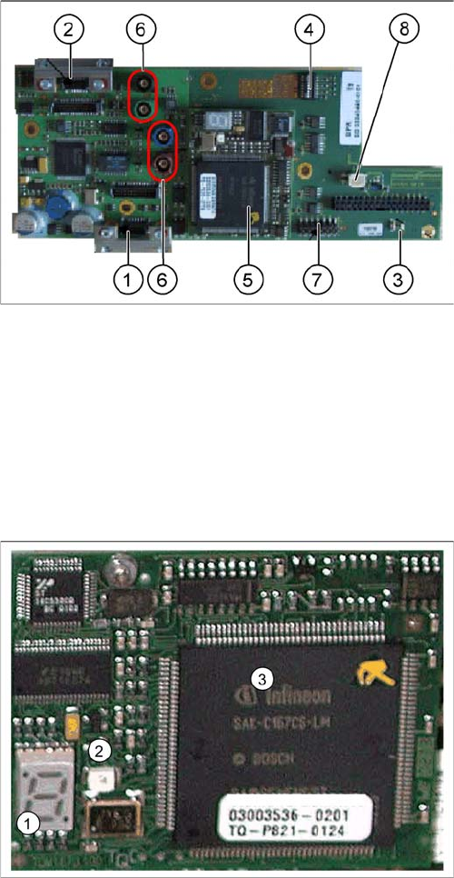
6.2.3.2 Vision Board (Digital)
Vision Board (Digital)
The Vision processor board is mounted on the gantry head distributor board. This PCB is used for all
four gantries.
See also
6.2.4.2 DIP Switch on Vision Board [ ➙ 205]
6.2.3.3
6.2.3.3 CAN 16 bit processor board (TQ module)
CAN 16 bit processor board (TQ module)
Description of 7-segment display (normal operation "." flashes):
▪ After switch ON the machine appears " 0 " on the display
▪ Display "b" --> BIOS was started.
▪ Display flashes alternatively between "b" and "." --> no application available or unable to start appli-
cation.
▪ Display " -I " and " I- " application was loaded.
▪ "." flashes on the display --> ready for operation.
Vision board
Legend
1. X8 Connector illumination and video signals PCB
camera
2. X3 Connector illumination and video signals compo-
nent camera
3. LEDs P15V - 15Volt / Vcc - Power supply Vision
board
4. DIP switch
5. CAN processor 16 bit (TQM module)
6. Connector X22 - X25 - Connectors for the video cable
to the trailing cable
7. Connector X11 for download
8. Voltage supply 11 VDC, measurable
16 bit processor (TQ module)
Legend
1. 7 Segment display
2. LED for manual RESET of processor
3. 16 bit processor
The 16 BIT CAN processor is used for various different
functions in the following units:
(see chapter communication and control too)
▪ Visionboard, communication and control via the CAN
Bus to the Vision computer.
▪ Gantry head distributor, control of head processes
and vacuum