SIPLACE D4-D4i 工程师手册_EN.pdf - 第180页
Service Work C&P12 Placement Head 4.5.20 Replacing the Control Board for the Nozzle Changer 6/12 [00317353-xx] 180 Service Manual SIPLACE D4/D4i 4.5.20 4 . 5 . 2 0 R e p la c in g t h e C o n t r o l B o a r d f o r …
Service Work
4.5.19 Replacing the RSF Digital Rotary Encoder (DP Axis) [00335990-xx] C&P12 Placement Head
Service Manual SIPLACE D4/D4i 179
See also
4.5.2 Removal/Installation of Head Front Part [ ➙ 143]
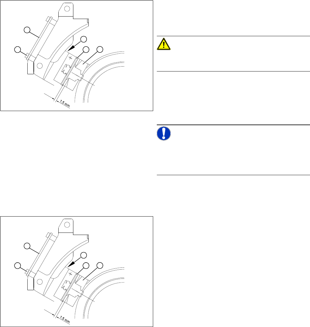
► Adjust the rotary encoder, so that the distance be-
tween the rotary encoder window and the incremental
disk on the sleeve is 1.5 mm.
Proceed as follows:
CAUTION!
Sensitive component!
RISK OF BREAKING THE INCREMENTAL DISK
► Carefully push the tapered end of the test probe be-
tween the window of the incremental encoder (1) and
the incremental disk (2).
► Loosen the fixing screws for the incremental encoder,
if you can not push the test probe in easily.
NOTICE!
The test probe has a blunt and a tapered end. Only push
the tapered end of the test probe between the incremen-
tal encoder and incremental disk of the sleeve, to avoid
scratching the disk and thus causing counting errors.
► Carefully push the rotary encoder towards the incre-
mental disk and along the stop edge (A) until the test
probe lies flat against the incremental disk (2) and the
window of the rotary encoder (1).
► Fix the rotary encoder in place using the two M2.5x8
hexagon socket-head screws.
► Carefully pull the test probe out of the gap.
► Remove the gauge for the star.
► Remove the sleeve from the star.
► Use the two M2.5x4 hexagon socket-head screws (4)
to fasten the RSF board (3).
► Connect the plug connector to the slot on the interme-
diate distributor.
► Place the black blanking cap over the RSF board.
► Fit the front part of the C&P head.
► Test the function of the rotary encoder to make sure
that it is working correctly.
A
1
4
3
2
A
1
4
3
2
Service Work
C&P12 Placement Head 4.5.20 Replacing the Control Board for the Nozzle Changer 6/12 [00317353-xx]
180 Service Manual SIPLACE D4/D4i
4.5.20
4.5.20 Replacing the Control Board for the Nozzle Changer 6/12 [00317353-xx]
Replacing the Control Board for the Nozzle Changer 6/12 [00317353-xx]
Overview
4.5.21
4.5.21 Checking the Cable Routing
Checking the Cable Routing
SIPLACE D1/D2 as example
Correct cable routing to and from the placement head is essential for long and accurate operation.
The high acceleration of the gantries can cause wear and damage to the connection leads.
▪ Cover unused connector strips with plastic caps:
Flat ribbon cables and coax leads can be damaged by unused connector strips. Make sure you at-
tach plastic caps.
Use dummy plugs for this [00368931-xx].
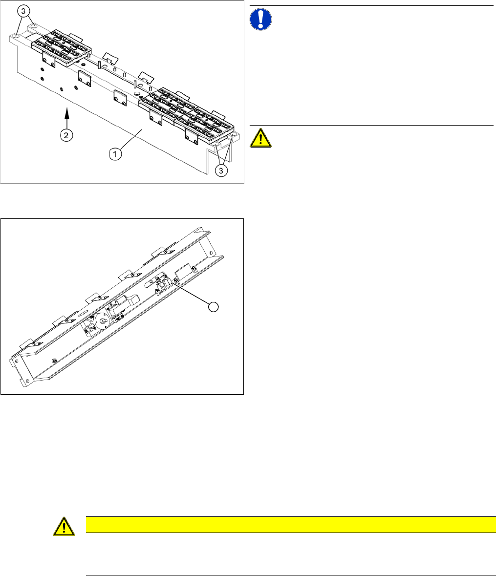
Nozzle changer for C&P12 (D4 shown as example)
NOTICE! The D1/D2 nozzle changers are just 1
magazine longer than those used for the D4. The struc-
ture is identical.
Legend
1. Nozzle changer 12 segments
2. Control board (installed on the underside)
3. 4 x fastening screws
CAUTION! The control board is also used for the
6-segment nozzle changer.
► Remove the nozzle changer from the machine. The
control board is situated on the underside of the noz-
zle changer.
Nozzle changer for C&P12 - viewed from below (D4
shown as example)
► Disconnect the control board (1) from the electrical
system.
► Loosen the fastening screws and remove the control
board .
► Fit the new control board and reconnect to the elec-
trical system.
► Fit the nozzle changer in the machine.
► Measure the nozzle changer with SITEST.
1
CAUTION
Check the cable routing!
Incorrect cable routing or poor fixture of the connection cables can cause mechanical damage.
This can then lead to malfunctions, non-reproducable errors and machine standstill.
Service Work
4.5.21 Checking the Cable Routing C&P12 Placement Head
Service Manual SIPLACE D4/D4i 181
▪ Position cable ties correctly:
Cables ties should be positioned so that the cables can be fastened properly and are guided past
any sharp edges.
▪ Cable clamps for flat ribbon cable:
If run together, narrow flat ribbon cables should be placed under wider ones.
The cables should not cross over one another under the clamp.
4.5.21.1
4.5.21.1 Cable Routing for Gantry Head Distributor Board
Cable Routing for Gantry Head Distributor Board
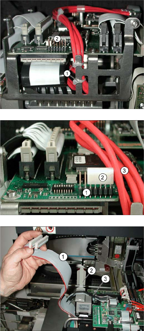
SIPLACE D1/D2 as example
Position cable ties correctly.
The coax camera cables to the gantry head distributor
need to be fixed with cables ties at the side.
The diagram shows the optimum position (1) for two ca-
ble ties, so that the cables do not touch the connector
strip (2).
▪ However, the connector strip (2) should still be fitted
with a dummy plug for safety purposes.
Using a dummy plug
▪ The connector strip (1) needs to be covered.
▪ Use the "dummy plug" [00368931-xx] (2) for this.
▪ Position the dummy plug (2) so that the connectors
pointing towards the cable (3) to be protected are
covered.
Wide flat ribbon cables are run above narrow ones
▪ If run together, narrow flat ribbon cables (3) must be
run under wider ones (1).
▪ Finally, carefully close the clamp.