SIPLACE D4-D4i 工程师手册_EN.pdf - 第241页
Settings 6.5.12 Conveyor Control TSP 301 Conveyor Service Manual SIPLACE D4/D4i 241 6.5.12 6 . 5 . 1 2 C o n v e y o r C o n t r o l T S P 3 0 1 Conveyor Control TSP 301 6.5.12.1 6 . 5 . 1 2 . 1 J u m p e r S e t t in g …
Settings
Conveyor 6.5.11 Lifting Table Functions
240 Service Manual SIPLACE D4/D4i
⇨ Lifting table up: 500 ms +/-20
ms (without lifting table plate ~450 +/-20 ms DT / ~360 +/-20 ms ET)
⇨ Lifting table down: 480 ms +/-20
ms (without lifting table plate ~550 +/-20 ms DT / ~600 +/-20 ms ET)
► If malfunctions occur during the downwards movement or if the board is shaken, reduce the lowering
speed accordingly.
Setting valve anticlockwise: Decrease the lifting table moving time
Setting valve clockwise: Increases the lifting table moving time
6.5.11.2
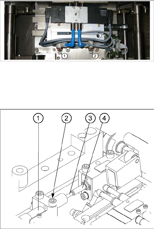
6.5.11.2 Setting the Lifting Table Unit [00358684-05]
Setting the Lifting Table Unit [00358684-05]
Legend
1. (3) adjust valve downwards
2. (4) adjust valve upwards
Setting the damping unit
The damping unit (1) allows the lifting table to move gen-
tly upwards. When the PCB is clamped, it also prevents
excessive bounce by the PCB.
► Check whether the damping unit is fixed with the lock-
nut (2) in the mounting block and that the plunger (3)
of the damping unit is just touching the actuator (4).
In this default setting, the lifting table should move up
gently.
► If this is not the case, loosen the locknut at the mount-
ing block and turn the damping unit approx. one rota-
tion into the mounting block..
► Move the lifting table upwards, with the help of the
software.
► The lifting table should move gently upwards.
The PCB clamping should not engage audibly and
there should be no PCB clamping error message.
► Check the speed of the lifting table and correct where
necessary.
Settings
6.5.12 Conveyor Control TSP 301 Conveyor
Service Manual SIPLACE D4/D4i 241
6.5.12
6.5.12 Conveyor Control TSP 301
Conveyor Control TSP 301
6.5.12.1
6.5.12.1 Jumper Settings for TSP 301
Jumper Settings for TSP 301
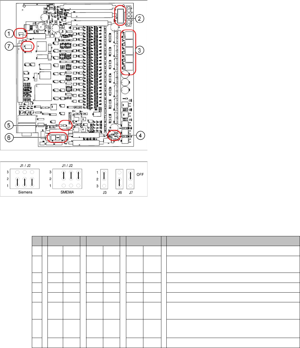
DIL switch S4 at TSP 301
* Switches 1 and 2 set the hardware ID 5 for D4/D4i machines and hardware ID 6 for X4I, X series, HF
and D3.ID 7 for Width Adjustment Unit
Legend
1. J7 CAN bus 1 terminating resistor
2. F6 Main Fuse TSP 301
3. F1 - F5 Fuses for the conveyor motors
4. J3 interference loop
5. J6 CAN bus 2 terminating resistor (not used)
6. J2, J1 successor/predecessor station
7. S4 DIL switch
Jumper J1, J2 "downstream/upstream station" at TSP
301
Legend
▪ J1 predecessor station
▪ J2 successor station
▪ J3 interference loop (EMERGENCY STOP on pro-
ductivity lift also switches the placement machine off)
▪ J6 CAN bus 2 terminating resistor (not used)
▪ J7 CAN bus 1 terminating resistor
S X4I D4 X/D3/HF Comments
1* ON ON ON ON
2* OFF ON OFF ON = SIPLACE D4/D4i, OFF: SIPLACE X, HF, D3,
X4I
3 OFF OFF OFF OFF= clamping sensor is no longer used
4ONONOFF OFFONON = quad lane, OFF: default conveyor
5 OFF OFF OFF Not in use
6 OFF ON OFF OFF ON OFF: Default conveyor, ON: quad lane (conveyor
edges fixed on outside)
7 OFF OFF OFF OFF: With width adj unit
ON: Without width adj. unit
8 OFF OFF OFF Not in use
Settings
Conveyor 6.5.12 Conveyor Control TSP 301
242 Service Manual SIPLACE D4/D4i
6.5.12.2
6.5.12.2 Conveyor Control TSP 301 with Siemens Interface
Conveyor Control TSP 301 with Siemens Interface
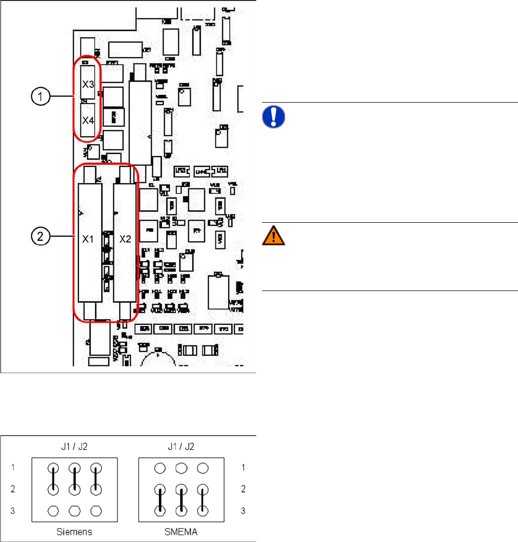
TSP 301 SMEMA --> Siemens
Legend
1. 10-pin plug for SMEMA interface
X3: upstream station
X4: successor station
2. Connection for Siemens interface
X1: upstream station
X2: successor station
NOTICE! Standard / Option
The SMEMA interface is a standard on all X machines
and the Siemens interface is optional.
The Siemens interface is a standard on all D/Di machines
and the SMEMA interface is optional. The SMEMA inter-
face requires an adapter when used with the D1/2/4/D1i/
D2i/D4i.
WARNING! Risk of irreparable damage to the
TSP board!
The 10 pin Locking clip plug of SMEMA connections must
be disconnected from the TSP 301!
Application: no modification.
Following modification are necessary for using the Sie-
mens interface:
► JumperJ1 / J2: need to be moved (see following dia-
gram).
► Disconnect the connector X3 and X4 on the TSP 301!
► Connect the Siemens interface cable on the connec-
tor X1 and X2.
Jumper J1 and J2 (Siemens/SMEMA)