SIPLACE D4-D4i 工程师手册_EN.pdf - 第38页
Overview Component Handling 3.4.2 Cutter 38 Service Manual SIPLACE D4/D4i 3.4.2.2 3 . 4 . 2 . 2 O v e r v ie w : M e c h a n ic a l C o n s t r u c t io n Overview: Mechanical Construction Overview: of Pneumatic Cutter V…

Overview
3.4.2 Cutter Component Handling
Service Manual SIPLACE D4/D4i 37
3.4.2
3.4.2 Cutter
Cutter
3.4.2.1
3.4.2.1 Safety Instructions
Safety Instructions
DANGER
The safety instructions in the chapter "Operational Safety" in the operating manual and this ser-
vice manual take priority.
The machine is supplied with
219/380 V +/- 5% or
230/400 V +/- 5% or
239/415 V +/- 5% or
117/204 V +/- 5% or
133/230 V +/- 5%,
50/60 Hz mains voltage.
Inside the machine base this is true even while the master switch is turned off.
► The machine has to be switched OFF and disconnected from the line before you perform
any work in the area of the cutter.
► In addition, the compressed air supply must be turned off at the main valve of the com-
pressed air unit in the machine base and the compressed air lines must be bled by actuating
the needle valve on the compressed air unit.
WARNING
► Wear appropriately thick protective gloves when working near the blades/the tape deflector!
► There is a high risk of injury from stationary blades and moveable blades and from the tape
deflector of the cutter, even when the machine has been turned off!
Overview
Component Handling 3.4.2 Cutter
38 Service Manual SIPLACE D4/D4i
3.4.2.2
3.4.2.2 Overview: Mechanical Construction
Overview: Mechanical Construction
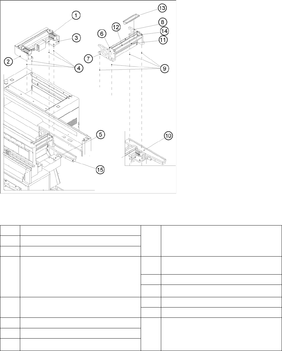
Overview: of Pneumatic Cutter Version 04 and Empty-Tape Duct Version 03
Legend
*) Loosen these screws only when removing/installing the cutter.
See also
4.3.2.5 Exchanging the Pneumatic Cutter [ ➙ 83]
1 "Pneumatic cutter" 9 Fastening of "empty-tape duct assembly":
2 socket hex head cap screws M 4 x 16
each on left and right
2 Retaining bracket for cutter, left
3 Retaining bracket for cutter, right
4 Fastening of the cutter,
2 socket hex head cap screws M6 x 25
each on left and right *)
Re-install any disks or plates that were pre-
viously removed.
10 Mounting surface for the "empty-tape duct
assembly" on the machine base
11 Baffle, inside
12 Baffle, outside
5 Mounting surface for cutter on the machine
base
13 Reject box for nozzles
14 Reject box (profile)
6 Empty-tape duct assembly 15 Stop buffer assembly on left and right-hand
side of the machine base,
Fastening: 2 socket hex head cap screws
M8 each on left and right
7 Side panel (left) of the empty-tape duct
8 Side panel (right) of the empty-tape duct
Overview
3.4.2 Cutter Component Handling
Service Manual SIPLACE D4/D4i 39
3.4.2.3
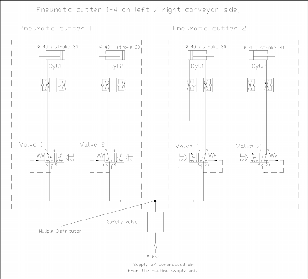
3.4.2.3 Diagrams of Pneumatic System and Functional Sequence
Diagrams of Pneumatic System and Functional Sequence
Diagram of Pneumatic System: Cutter per conveyor edge