SIPLACE D4-D4i 工程师手册_EN.pdf - 第94页
Service Work Component Handling 4.3.2 Cutter 94 Service Manual SIPLACE D4/D4i ► Using the feeler gauge , check the gap between tape deflector an d movable blade, over the entire length and width of the blade: ⇨ Th e 0.05…
Service Work
4.3.2 Cutter Component Handling
Service Manual SIPLACE D4/D4i 93
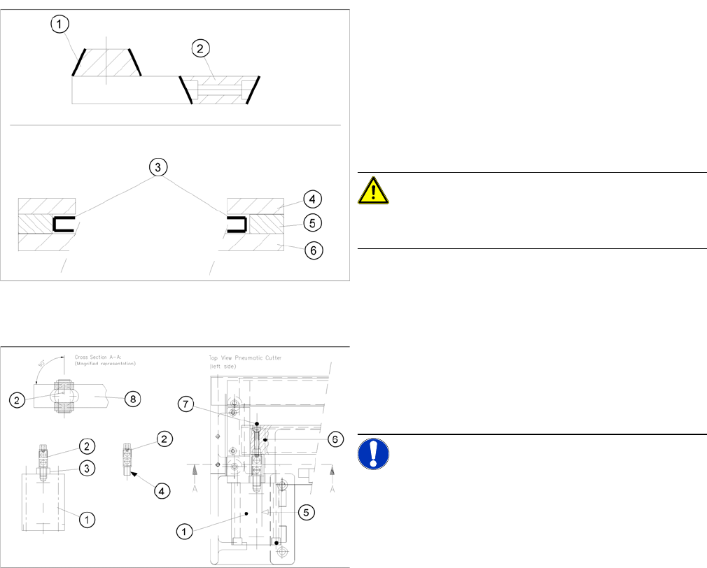
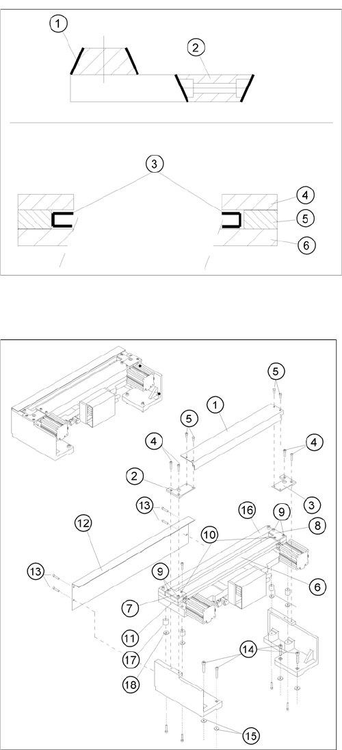
Mounting new blades, mounting position of the blades,
slide surfaces to be greased
Legend
1. Stationary blade
2. Moveable blade
3. Slide surfaces to be greased before installing the
movable blade
4. Holddowns
5. Spacer
6. Contact surface
CAUTION! Make sure the cutter is in the correct
rotary position (see the slant of the blade).
Tighten the screws to the correct torque.
► Insert the movable blade into the cutter, in the correct
rotational position, while pushing it into its original
mounting position.
► Apply Loctite no. 243 to the two M4 screws (7), to fas-
ten the joint in the moveable blade.
► Reinstall these screws, on the left and right, in the
movable blade.
NOTICE! Make certain that the midline / open-
end wrench surface of the articulated joint is at right an-
gles to the slide surface of the movable blade (5, 6), so
that the articulated joint can slide smoothly in the slot (=
prevents turning) of the movable blade .
► Use an SW 10 open-ended wrench to push against
the relevant articulated joint and tighten both screws
to the correct torque.
► Place the two new spacers to the left and right of the
moveable blade. The spacer side marked with a num-
ber must face towards the blade.
⇨ The spacers and blades are matched !
Service Work
Component Handling 4.3.2 Cutter
94 Service Manual SIPLACE D4/D4i
► Using the feeler gauge, check the gap between tape deflector and movable blade, over the entire
length and width of the blade:
⇨ The 0.05 mm feeler gauge should fit through the gap.
⇨ The 0.25 mm feeler gauge should not fit through the gap.
If the gap is not correct, check:
► Whether the wrong holddowns has been installed (with function status < 03).
The holddowns are those designed for cutters with function status -04 (= with tape deflector).
► Whether the blades, tape deflector etc. were cleaned before installation
If the gap is correct:
► Carefully fold the cover plate (with cover plate holders installed) back over the tape deflector.
Mounting new blades, mounting position of the blades,
slide surfaces to be greased
► Grease the contact / slide surfaces for the movable
blade exactly in the area shown (3).
⇨ Do not lubricate the blades themselves.
► Place an adjustment plate (0.5 to 1.0 mm thick) on
the left and right, between the spacer and the face of
the movable blade.
► Place the holddowns previously removed back on the
new spacers.
⇨ The version 03 holddowns match the version 04
cutters (= with tape deflector)!
► Reinstall the previously removed deflector holder (=
with tape deflector) and initially tighten the 4 hexagon
socket head screws (9) hand-tight.
► Push the spacers (with inserted adjustment plate) to-
wards the movable blade - up to the stop but not until
they exert pressure against it, otherwise it would no
longer be possible to remove the adjustment plates.
⇨ The maximum permissible gap is 1.0 mm.
► In this position, tighten all 4 screws on the tape de-
flector holders crosswise.
⇨ Tighten the screws to the correct torque.
► Remove the two shim rings.
► Insert the new stationary blade in the correct position
((see diagram) and screw tight (2 screws).
⇨ Tighten the screws to the correct torque.
Service Work
4.3.2 Cutter Component Handling
Service Manual SIPLACE D4/D4i 95
See also
4.3.2.7 Replacing the Stationary Blade and Movable Blade incl. Spacers [ ➙ 91]
4.3.2.4.1 Tightening Torques for Cutter Screws [ ➙ 83]
6.4.3 Check the gap between the empty-tape baffle, inside and the leading edge of the tape deflec-
tor. [ ➙ 223]
4.3.2.14 Final Steps [ ➙ 107]
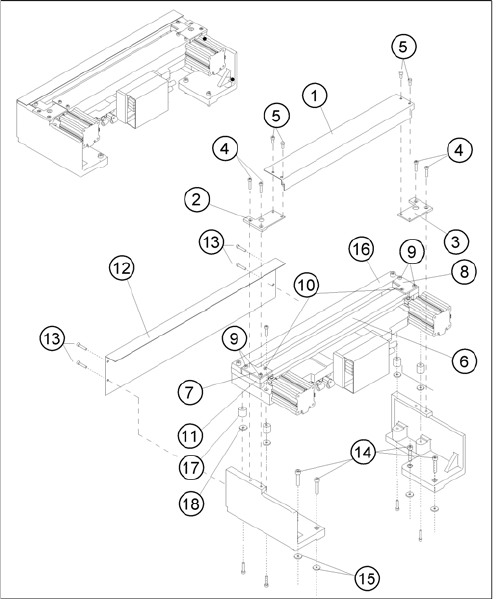
► Make certain that the edges are parallel, then screw
the cover plate holder to the cutter (two M4 screws
each (7, 9)):
⇨ -> Do not pinch or put strain on the cables.
► Install the cover plate on the stationary blade (4 M4
screws (12, 13)).
► Remove the parallel clamps from the cutter or dis-
mantle the cutter from the mounting plate.
► Fit the cutter back into the machine. (See "4.3.2.5 Ex-
changing the Pneumatic Cutter" [ ➙ 83].)
► Fit the empty-tape duct assembly and check the gap
between the empty-tape baffle, inside and the leading
edge of the tape deflector.
► Perform the appropriate “Final Steps”.