SIPLACE D4-D4i 工程师手册_EN.pdf - 第50页
Service Work Electrical System 4.1.2 Measuring the Power Supply Unit 50 Service Manual SIPLACE D4/D4i M8 hexagon socket-he ad screw to lock the unit ► Pull the unit out a s far as the stop. 4.1.1.4 4 . 1 . 1 . 4 W h a t …

Service Work
4.1.1 Measuring Voltages on the Power Supply Unit Electrical System
Service Manual SIPLACE D4/D4i 49
4
4 Service Work
Service Work
4.1
4.1 Electrical System
Electrical System
4.1.1
4.1.1 Measuring Voltages on the Power Supply Unit
Measuring Voltages on the Power Supply Unit
4.1.1.1
4.1.1.1 Safety Instructions
Safety Instructions
4.1.1.2
4.1.1.2 Tools and equipment required
Tools and equipment required
▪ Digital voltmeter, class 1.5
Measurement range:
– AC voltage: 750 V
– Alternating current: 40 A
– DC voltage: 300 V
– Direct current: 30 A
– Resistance: 200 Ohm - 20 MOhm
▪ Test cable with test probes or terminals
▪ Circuit diagram folder SIPLACE D4 [00194752-xx]
▪ DIN 911 Allen key, size 6
▪ 3 mm key, double-bit, DIN 43668-J33 (00304191-xx)
4.1.1.3
4.1.1.3 Preparing the power supply unit for measurement
Preparing the power supply unit for measurement
The power supply unit and main switch are located in the machine base. In front of the unit there is a set
of safety doors which can be opened with the double-bit key.
The unit is fixed to the machine base using an M8 hexagon socket-head screw.
To measure the power supply, proceed as follows:
► Switch the placement system off at the main switch.
► Open the safety doors with the double-bit key.
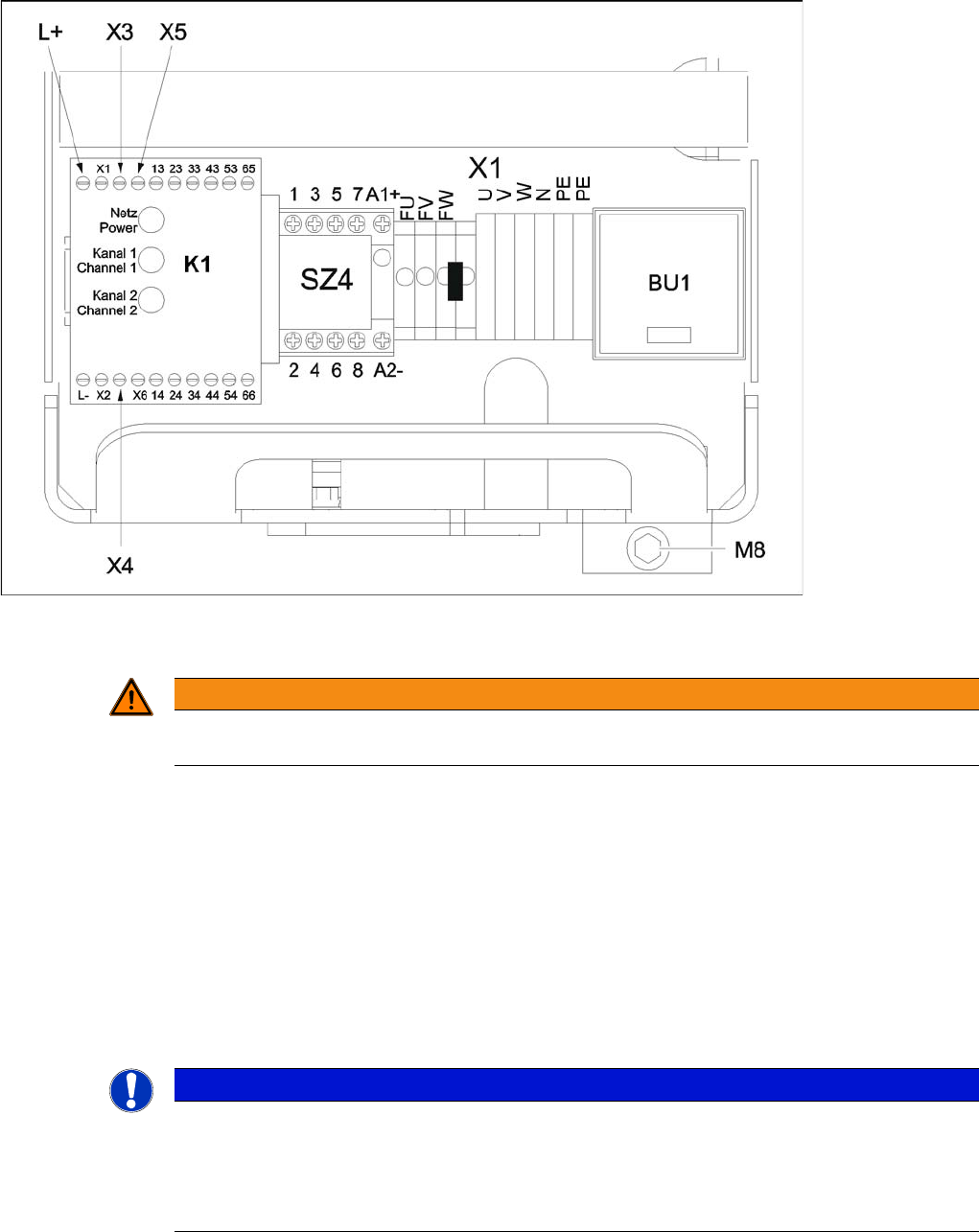
► Loosen the M8 lock screw, fastening the underside of the unit at the front (see fig).
WARNING
Nonobservance of these safety instructions may cause injury to personnel and damage to the
machine!
The service work described in this manual may only be performed by specially trained service
technicians, with appropriate qualifications and expertise.
► Please observe the safety instructions in the Operating Manual for all service work!
DANGER
The machine is supplied with 3 x 400 V~ (or 3 x 204 V~ / 3 x 230 V~ / 3 x 380 V~ / 3 x 415 V~)
± 5 %, 50/60 Hz mains voltage.
Consequently, parts of the system carry potentially lethal voltages, even when it is switched off
at the main switch.
Incorrect handling of the machine can therefore result in death, severe injury or considerable
damage to equipment.
Measurements and repairs must always be carried out by appropriately qualified personnel.
► Always follow the safety instructions in chapter 2 of this manual.
► Always follow the applicable accident prevention and VDE regulations (particularly DIN EN
60 204 part 1) or the regulations specific to your country.
Service Work
Electrical System 4.1.2 Measuring the Power Supply Unit
50 Service Manual SIPLACE D4/D4i
M8 hexagon socket-head screw to lock the unit
► Pull the unit out as far as the stop.
4.1.1.4
4.1.1.4 What To Do After Completing Service Work
What To Do After Completing Service Work
► Fit the power supply unit and fix in place with the M8 hexagon socket-head screw.
► Make sure that you do not pinch the cable when inserting the board!
► Lock the safety doors.
► Remove the key and keep in a safe place.
► Switch the placement system on at the main switch and start it up.
4.1.2
4.1.2 Measuring the Power Supply Unit
Measuring the Power Supply Unit
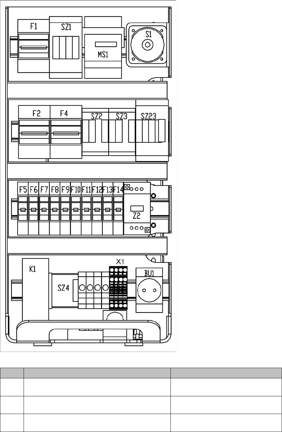
For the position of the modules, refer to "4.1.2.1 Front View" [ ➙ 51].
The inputs to the modules all have odd numbers and the outputs have even numbers.
In the case of fuses (F1, etc), the input is always on the underside of the module, whereas with contac-
tors (SZ1, etc) and motor circuit-breakers (MS1 ...), it is always at the top.
WARNING
Make sure that the main power cable and supply cables in the machine are not trapped and
that the insulation is not damaged.
NOTICE
The placement system must be started in order to take these measurements.
This means that the protective covers and component flaps must be closed and the changeover
tables docked. The emergency stop button must be released and the start button pressed. If
this is not the case, the operating voltages will not be switched through to the servo amplifiers,
lifting tables, etc.
Service Work
4.1.2 Measuring the Power Supply Unit Electrical System
Service Manual SIPLACE D4/D4i 51
4.1.2.1
4.1.2.1 Front View
Front View
Power supply unit - front panel - parts overview
Item Designation Voltages
S1 Main switch 3LC4/3-pole/40A 3 x 204 V~ / 3 x 230 V~ / 3 x 380 V~
/ 3 x 400 V~ / 3 x 415 V~
MS1 Motor circuit-breaker PKZ2/3-pole/40A 3 x 204 V~ / 3 x 230 V~ / 3 x 380 V~
/ 3 x 400 V~ / 3 x 415 V~
SZ1 Contactor 3RT10/24VDC/size S2 3 x 204 V~ / 3 x 230 V~ / 3 x 380 V~
/ 3 x 400 V~ / 3 x 415 V~