SIPLACE D4-D4i 工程师手册_EN.pdf - 第39页
Overview 3.4.2 Cutter Component Handling Service Manual SIPLACE D4/D4i 39 3.4.2.3 3 . 4 . 2 . 3 D ia g r a m s o f P n e u m a t ic S y s t e m a n d F u n c t io n a l S e q u e n c e Diagrams of Pneumatic System and Fu…
Overview
Component Handling 3.4.2 Cutter
38 Service Manual SIPLACE D4/D4i
3.4.2.2
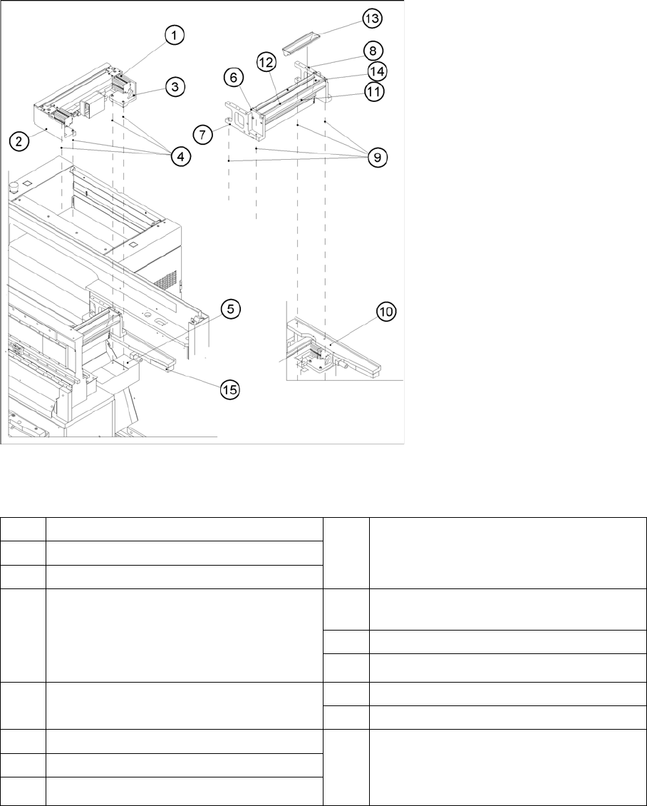
3.4.2.2 Overview: Mechanical Construction
Overview: Mechanical Construction
Overview: of Pneumatic Cutter Version 04 and Empty-Tape Duct Version 03
Legend
*) Loosen these screws only when removing/installing the cutter.
See also
4.3.2.5 Exchanging the Pneumatic Cutter [ ➙ 83]
1 "Pneumatic cutter" 9 Fastening of "empty-tape duct assembly":
2 socket hex head cap screws M 4 x 16
each on left and right
2 Retaining bracket for cutter, left
3 Retaining bracket for cutter, right
4 Fastening of the cutter,
2 socket hex head cap screws M6 x 25
each on left and right *)
Re-install any disks or plates that were pre-
viously removed.
10 Mounting surface for the "empty-tape duct
assembly" on the machine base
11 Baffle, inside
12 Baffle, outside
5 Mounting surface for cutter on the machine
base
13 Reject box for nozzles
14 Reject box (profile)
6 Empty-tape duct assembly 15 Stop buffer assembly on left and right-hand
side of the machine base,
Fastening: 2 socket hex head cap screws
M8 each on left and right
7 Side panel (left) of the empty-tape duct
8 Side panel (right) of the empty-tape duct
Overview
3.4.2 Cutter Component Handling
Service Manual SIPLACE D4/D4i 39
3.4.2.3
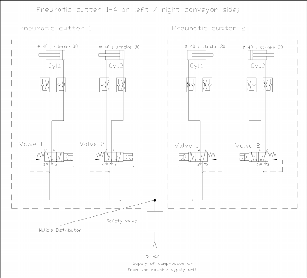
3.4.2.3 Diagrams of Pneumatic System and Functional Sequence
Diagrams of Pneumatic System and Functional Sequence
Diagram of Pneumatic System: Cutter per conveyor edge
Overview
Modular Conveyor 3.5.1 Module Overview
40 Service Manual SIPLACE D4/D4i
3.5
3.5 Modular Conveyor
Modular Conveyor
3.5.1
3.5.1 Module Overview
Module Overview
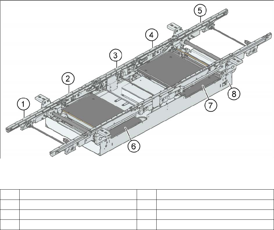
PCB conveyor – single conveyor (D3/D4)
Legend
The modular conveyor system consists of an input conveyor, two placement areas, the intermediate con-
veyor and the output conveyor. Each conveyor system has automatic width adjustment and a lifting table
to clamp the PCB in place. The standard machine is equipped as a single PCB conveyor. A dual PCB
conveyor system is optionally available. Depending on individual requirements, either the left or right
conveyor side can be selected as the fixed conveyor side.
1 Input conveyor 5 Output conveyor
2 Placement area 1 6 Lifting table placement area 1
3 Intermediate belt 7 Lifting table placement area 2
4 Placement area 2 8 Assembly tray