SIPLACE D4-D4i 工程师手册_EN.pdf - 第127页
Service Work 4.4.10 Replacing the Lifting T able Stabilizer (Stabilizer Unit) [00358684-xx] PCB conveyor system Service Manual SIPLACE D4/D4i 127 4.4.10 4 . 4 . 1 0 R e p la c in g t h e L if t in g T a b le S t a b iliz…
Service Work
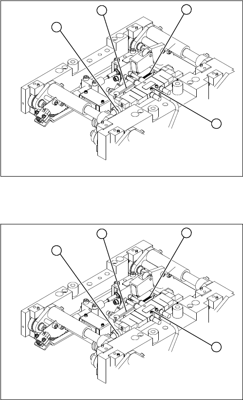
PCB conveyor system 4.4.9 Replacing the Complete Lifting Table Cylinder [00358703]
126 Service Manual SIPLACE D4/D4i
Removal
Installation
► Loosen the screw fastening the lifting table plate and
remove the lifting table plate from the lifting table unit.
► Loosen the fastening screws for the solenoid valve
(4) and remove it from the lifting table cylinder.
► Loosen the grub screw at the end position proximity
switch (1) and push the end position proximity switch
out of the lifting table cylinder guide rail (2).
► Loosen the locknut on the piston rod (3) and twist the
piston rod out until it releases itself from the actuator.
► Loosen and remove the two screws fastening the lift-
ing table cylinder (2).
4
1
3
2
► Insert and fasten the new lifting table cylinder (2) and
install the piston rod (3).
► Move the lifting table by hand to its end position.
► Switch the machine on.
► Push the end position proximity switch (1) into the
guide rail until the LED lights up.
► Fix this position with the grub screw.
► Install the solenoid valve (4) and the lifting table plate.
► Check the speed of the lifting table and correct where
necessary.
4
1
3
2
Service Work
4.4.10 Replacing the Lifting Table Stabilizer (Stabilizer Unit) [00358684-xx] PCB conveyor system
Service Manual SIPLACE D4/D4i 127
4.4.10
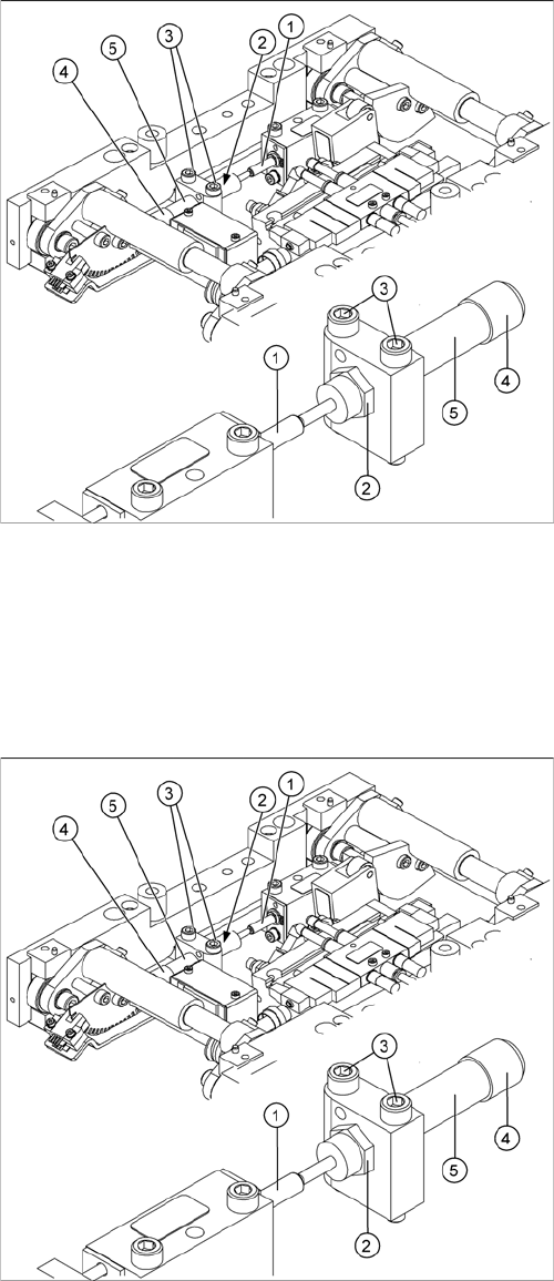
4.4.10 Replacing the Lifting Table Stabilizer (Stabilizer Unit) [00358684-xx]
Replacing the Lifting Table Stabilizer (Stabilizer Unit) [00358684-xx]
Overview
Tools and equipment required
▪ Torque wrench with plug-in ratchet [00386175-xx]
▪ Plug-in wrench 16 mm [00386177-xx]
Removal
1. Actuator
2. Locknut
3. Fastening screws
4. Handle
5. Stabilizer [00358684-xx]
The stabilizer enables the lifting table to be moved gently
upwards. It prevents the PCBs from being clamped in
with too much impact.
The stabilizer consists of the shock absorber [00367737-
xx] and the damping block [00367782-xx].
► Move the PCB conveyor to the position which gives
you best access to the lifting table.
► Move the Y gantries into the area outside the PCB
conveyor.
► Switch off the machine and secure it to prevent unau-
thorized reactivation.
► Loosen the screws fastening the lifting table plate and
remove the lifting table plate from the lifting table unit.
► Loosen the two screws (3) holding the stabilizer (5).
► Undo the locknut (2) and take the stabilizer by its han-
dle (4), twisting it out of the mounting block.
Service Work
PCB conveyor system 4.4.11 Replacing the Stepping Motor of the Width Adjustment System [00367174]
128 Service Manual SIPLACE D4/D4i
Installation and adjustment
4.4.11
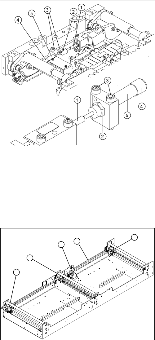
4.4.11 Replacing the Stepping Motor of the Width Adjustment System [00367174]
Replacing the Stepping Motor of the Width Adjustment System [00367174]
Overview
► Insert and twist the new stabilizer (5) until the plunger
just touches the actuator (1), so that the lifting table
can be gently moved upwards.
► Using the torque wrench:
Secure this position with the locknut (2) tightened to
8Nm.
► Check whether the stabilizer has been fixed onto the
mounting block with the locknut and that the stabilizer
plunger has a gap of approx. 0.1 mm to the actuator
(gap in untriggered mode). In this default setting, the
lifting table should move up gently.
► If this is not the case, loosen the locknut and turn the
stabilizer approx. one rotation into the mounting
block.
► Fit the lifting table plate.
► Start SITEST and move the lifting table up.
► The lifting table should move up gently i.e. you should
not hear the PCB clamping device audibly locking
into place and no clamping device error messages
should be issued.
► Check the speed of the lifting table cylinder and cor-
rect where necessary.
Legend
1. Width adjustment stepping motor
2. Toothed belt for the drive
3. Adjustment units 1, 2 and 3
3
3
1
3
2