SIPLACE D4-D4i 工程师手册_EN.pdf - 第133页
Service Work 4.4.15 Replacing the Proximity Switch for the Adjustment Unit [ 00363268 -xx] (applicable to modular PCB conveyor only) PCB conve yor syst em Service Manual SIPLACE D4/D4i 133 Removal/Installation 4.4.15 4 .…
Service Work
PCB conveyor system 4.4.14 Replacing the Cylinder Switch for the Adjustment Unit [00369016-xx]
132 Service Manual SIPLACE D4/D4i
Removal/installation
4.4.14
4.4.14 Replacing the Cylinder Switch for the Adjustment Unit [00369016-xx] (applicable to modular PCB conveyor only)
Replacing the Cylinder Switch for the Adjustment Unit [00369016-xx] (applicable to
modular PCB conveyor only)
Parts
▪ Cylinder switch of width adjustment 1 [00363267-xx]
▪ Cylinder switch of width adjustment 2 [00363291-xx]
Overview
► Move the PCB conveyor to the position which gives you best access to the adjustment system.
► Move the Y gantries into the area outside the PCB conveyor.
► Switch off the machine and secure it to prevent unauthorized reactivation.
► Switch off the compressed air supply.
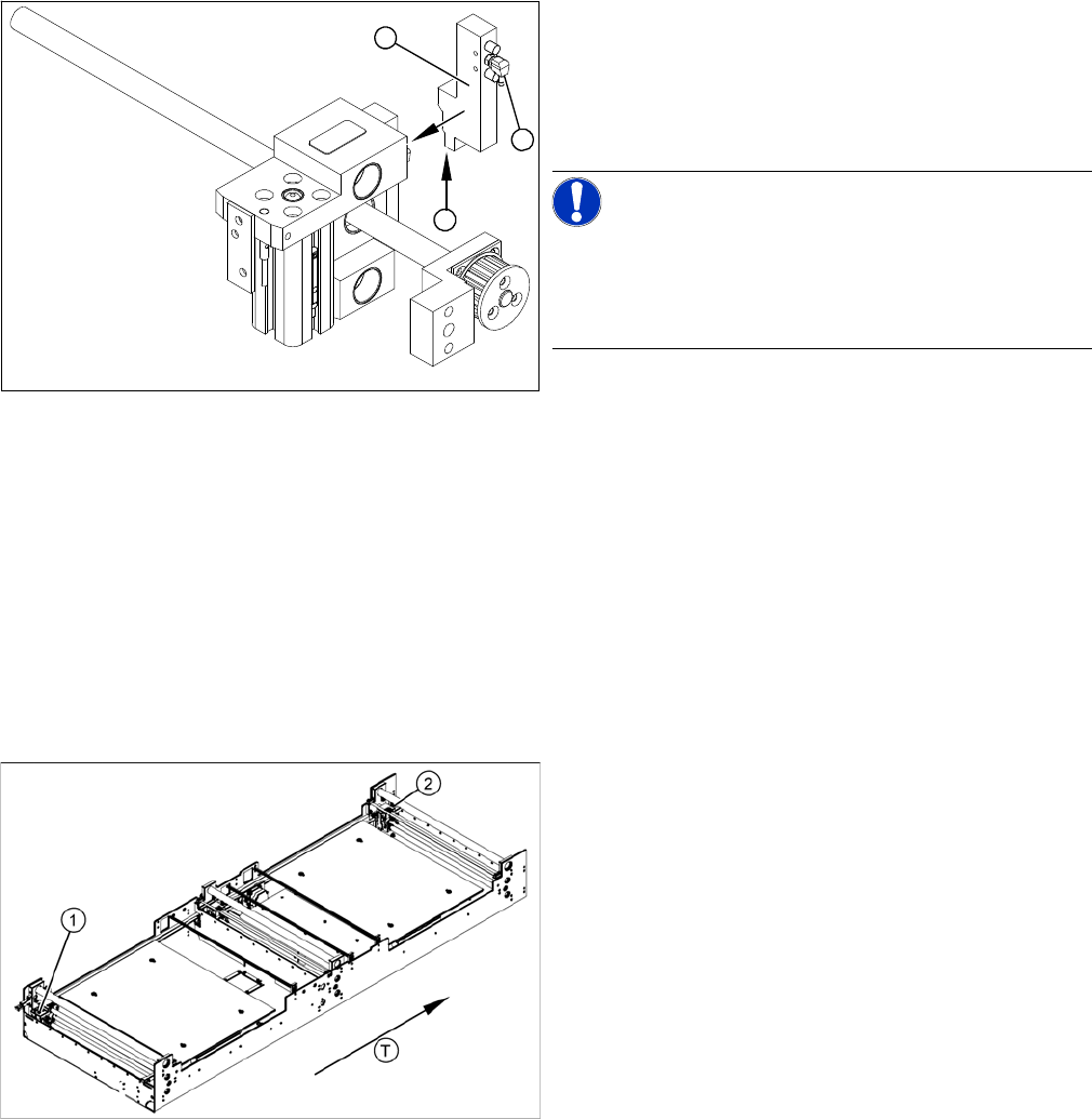
► Remove the compressed air connections (2).
► Loosen the two fastening screws and remove the so-
lenoid valve (3) from the short-stroke cylinder.
► Unthread the connection cable (1) as far as the rele-
vant assembly tub conversion board and unplug.
NOTICE! This might be somewhat complicated
depending on the routing of cables inside the machine
base.
You may wish to contact Siemens AG SMD Service re-
garding this work.
► Fit the new solenoid valve (3) and reconnect the sys-
tem to the electrical (1) and compressed air (2) sup-
plies.
1
3
2
The cylinder switch on the adjustment unit cylinder
should operate when the adjustment unit pin is pushed
out by the pneumatic cylinder and therefore connected to
the conveyor side. This signal enables the width adjust-
ment motor.
Legend
1. Adjustment unit 1
2. Adjustment unit 2
T = transport direction
Service Work
4.4.15 Replacing the Proximity Switch for the Adjustment Unit [00363268-xx] (applicable to modular PCB conveyor only) PCB conveyor system
Service Manual SIPLACE D4/D4i 133
Removal/Installation
4.4.15
4.4.15 Replacing the Proximity Switch for the Adjustment Unit [00363268-xx] (applicable to modular PCB conveyor only)
Replacing the Proximity Switch for the Adjustment Unit [00363268-xx] (applicable to
modular PCB conveyor only)
Parts
▪ Proximity switch for adjustment unit 1 [00363268-xx]
▪ Proximity switch for adjustment unit 2 [00363292-xx]
Overview
► Move the PCB conveyor to the position which gives you best access to the adjustment system.
► Move the Y gantries into the area outside the PCB conveyor.
► Switch off the machine and secure it to prevent unauthorized reactivation.
► Switch off the compressed air supply.
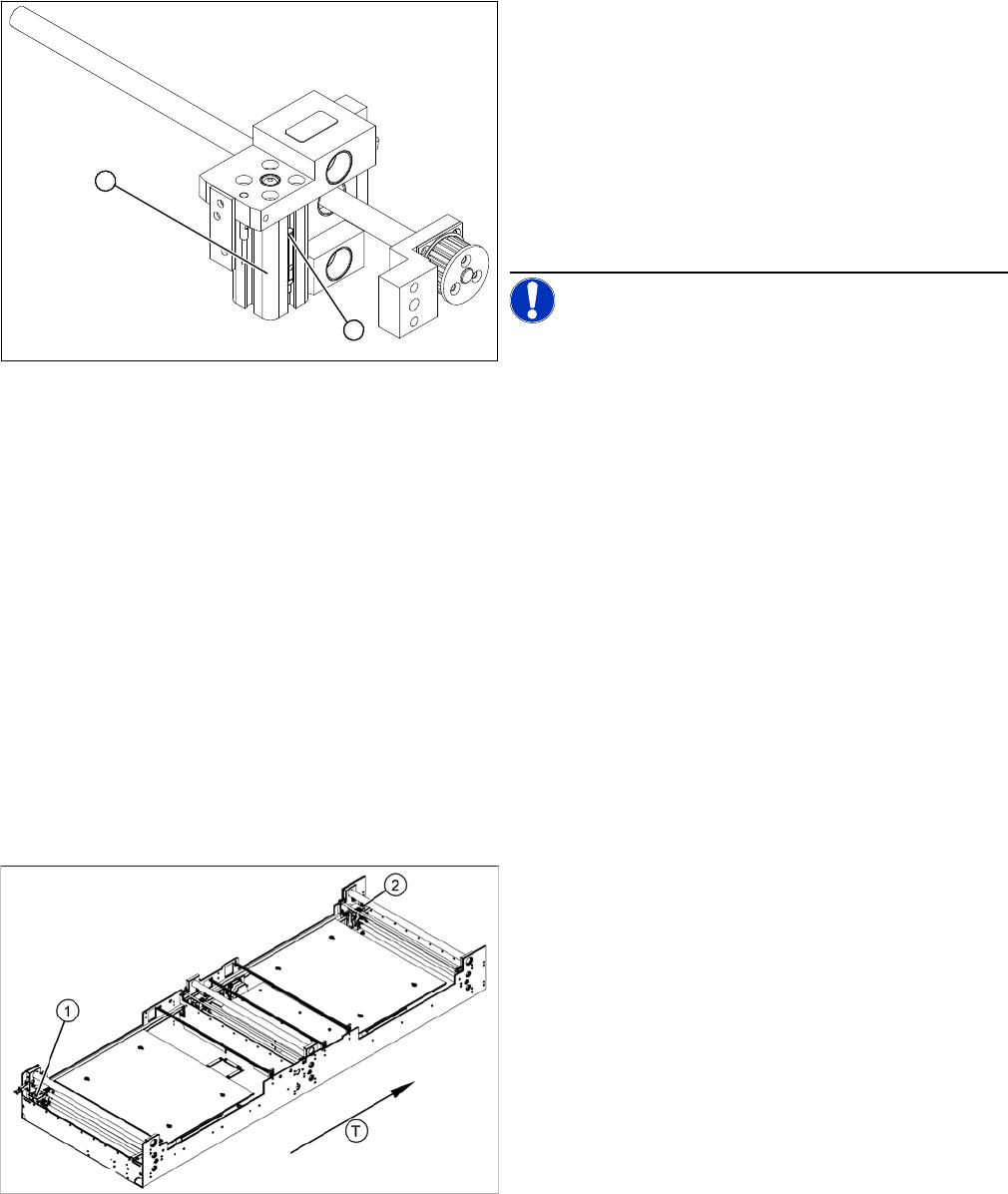
► Loosen the grub screw at the cylinder switch (1) and
push the cylinder switch out of the adjustment unit
guide rail (2).
► Unthread the connection cable as far as the conver-
sion board of the assembly tub.
► Run the connection cable of the new cylinder switch
(2).
► Insert the new cylinder switch into the guide rail.
► Switch the machine on.
NOTICE! The width adjustment system cylinder
switch is set in engaged mode.
► Move the width adjustment system until the cylinder
switch switches - LED (H36/H37).
► Engage the cylinder - i.e. the cylinders are moved to
the upper limit by the controls.
► Set the cylinder switch so that the LED lights up when
it is in engaged mode.
► Fix the position of the cylinder switch (2) with the grub
screw.
2
1
The proximity switch serves as a signal for controlling the
pneumatic valve of the adjustment unit. Once the switch-
ing point has been reached, the conveyor edge is con-
nected via the short-stroke cylinder.
Legend
1. Adjustment unit 1
2. Adjustment unit 2
T = transport direction
Service Work
PCB conveyor system 4.4.16 Replacing the Light Barriers for Transmitter and Receiver Modules
134 Service Manual SIPLACE D4/D4i
Removal/Installation
4.4.16
4.4.16 Replacing the Light Barriers for Transmitter and Receiver Modules [00370063]
Replacing the Light Barriers for Transmitter and Receiver Modules [00370063]
Parts
Please note the different item numbers for the individual light barriers - these are for the different lengths
of the connection cable.
Please consult the parts catalogue for the individual article numbers.
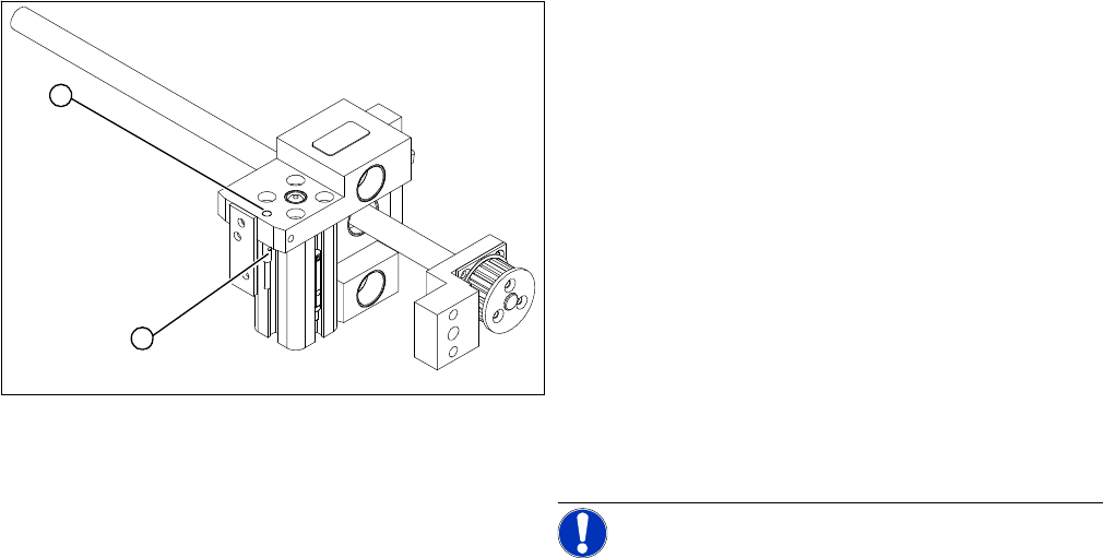
► Loosen the grub screw on the clamping device (1)
and unthread the connection cable as far as the con-
version board of the assembly tub.
► Fit the new proximity switch and reconnect the sys-
tem to the electrical system.
► Fix the proximity switch with the grub screw.
► Tighten the grub screw to a torque of 20 Ncm
(+3 Ncm). The proximity switch must be level with the
adjustment unit housing (2).
► The switching point is set at the actuator on the con-
veyor edge:
► Move the adjustment unit until it is under the convey-
or edge.
► Place a 4/10 mm distance gauge on the adjustment
unit, press the actuator onto the distance gauge and
tighten the screw.
NOTICE! This setting must be performed at all
conveyor edges.
► Use the SITEST program to calibrate the conveyor
edges.
2
1