SIPLACE D4-D4i 工程师手册_EN.pdf - 第140页
Service Work PCB conveyor system 4.4.18 Overview of the Electrical Components 140 Service Manual SIPLACE D4/D4i 4.4.18.2 4 . 4 . 1 8 . 2 C o n v e y o r C o n v e r s io n B o a r d [ 0 0 3 5 9 4 2 5 ] Conveyor Conversio…
Service Work
4.4.18 Overview of the Electrical Components PCB conveyor system
Service Manual SIPLACE D4/D4i 139
Removal /installation of receiver module
4.4.18
4.4.18 Overview of the Electrical Components
Overview of the Electrical Components
4.4.18.1
4.4.18.1 Conveyor Side Conversion Board [00359424]
Conveyor Side Conversion Board [00359424]
Overview
► Loosen the 2 screws fastening the receiver module
(1).
► Unthread the connection cable as far as the relevant
conversion board of the conveyor side.
► Unplug the conversion board of the conveyor side.
► Reconnect the conversion board of the conveyor side
to the power supply and rerun the connection cable
accordingly.
► Fit the new receiver module in the original position.
► Switch the machine on.
► Move the conveyor system to maximum width.
► Turn the 2 fastening screws to align the receiver cen-
trally to the transmitter diode. The entire height of the
transmitter diode laser beam must hit the receiver.
Please also refer to the adjustment instructions.
1
Legend
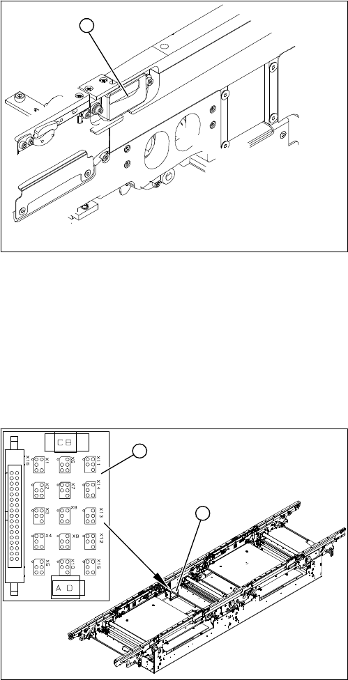
1. Conveyor side conversion board
2. Cover
The conversion boards for the conveyor sides (1) are sit-
uated on the respective conveyor sides, under a cover
(2).
For terminal assignment details, please refer to the cur-
rent version of the circuit diagram folder.
1
2
Service Work
PCB conveyor system 4.4.18 Overview of the Electrical Components
140 Service Manual SIPLACE D4/D4i
4.4.18.2
4.4.18.2 Conveyor Conversion Board [00359425]
Conveyor Conversion Board [00359425]
Overview
4.4.18.3
4.4.18.3 Lifting Table Conversion Board [00362766]
Lifting Table Conversion Board [00362766]
Overview
4.4.18.4
4.4.18.4 Conveyor Control TSP 301 [00370397]
Conveyor Control TSP 301 [00370397]
Overview
Legend
1. Conveyor conversion board
2. Cover
The conveyor conversion board (1) is situated in the vi-
cinity of the intermediate conveyor, under the cover (2).
For terminal assignment details, please refer to the cur-
rent version of the circuit diagram folder.
1
2
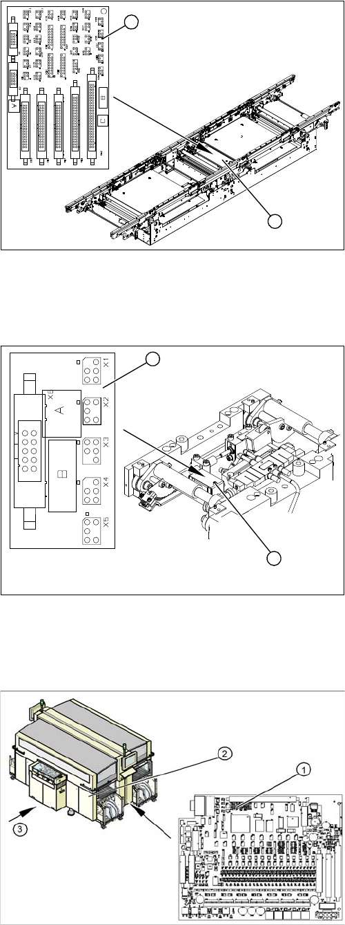
Legend
1. Lifting table conversion board
2. Cover
The lifting table conversion board (1) is situated on the
lifting table unit, under the cover (2).
For terminal assignment details, please refer to the cur-
rent version of the circuit diagram folder.
1
2
Legend
1. Conveyor Control TSP 301
2. Access to conveyor control
3. Transport direction
The conveyor control TSP 301 (1) is located in the sector
distributor 1 (2). The conveyor control is secured with a
screw-off cover.
For terminal assignment details, please refer to the cur-
rent version of the circuit diagram folder.
Service Work
4.5.1 Replacing the C&P12 Head (D4) C&P12 Placement Head
Service Manual SIPLACE D4/D4i 141
4.4.18.5
4.4.18.5 Extension Controller Board TSP 301E for Dual Conveyors [00370398]
Extension Controller Board TSP 301E for Dual Conveyors [00370398]
Overview
4.5
4.5 C&P12 Placement Head
C&P12 Placement Head
4.5.1
4.5.1 Replacing the C&P12 Head (D4)
Replacing the C&P12 Head (D4)
Overview
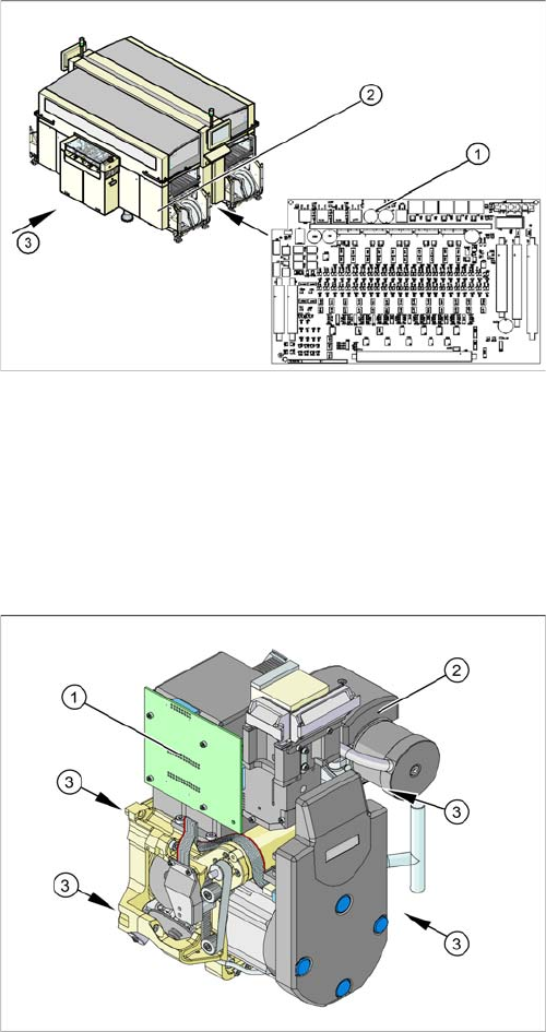
Legend
1. Conveyor control TSP 301E
2. Access to conveyor control
3. Transport direction
The extension card for the dual conveyor TSP 301E (1)
is located in the sector distributor 1 (2). The conveyor
control is secured with a screw-off cover.
For terminal assignment details, please refer to the cur-
rent version of the circuit diagram folder.
Legend
1. Illumination controller
2. Vacuum generator
3. 4 x fastening screws
Item number
▪ C&P head DLM3 with 12 segments [03041228-xx]
(C&P12 head)