SIPLACE D4-D4i 工程师手册_EN.pdf - 第208页
Settings C&P12 6.3.2 Boards at C&P12 208 Service Manual SIPLACE D4/D4i 6.3.2.2 6 . 3 . 2 . 2 L E D s o n g a n t r y h e a d d is t r ib u t o r LEDs on gantry head distributor Legend Display functions and signal…

Settings
6.3.2 Boards at C&P12 C&P12
Service Manual SIPLACE D4/D4i 207
6.3.2.1
6.3.2.1 8-fold DIP Switch of the gantry head distributor (incl. switch S1) – C&P6/12
8-fold DIP Switch of the gantry head distributor (incl. switch S1) – C&P6/12
Switch P0 and P1:
Gantry selection via switch P0 and P1
Switch S1:
▪ ON – Test mode (without delay)
▪ OFF – Default state (with delay of 3.6 ms+/- 300 us) means: Z axis moves downwards, the top LB is
released and the LB down is enabled after a delay of 3.6 ms.
See also
6.2.3.1.1 Description of LEDs on the Gantry Head Distributor [ ➙ 203]
6.2.3.1 Gantry Head Distributor [ ➙ 201]
6.3.2.2 LEDs on gantry head distributor [ ➙ 208]
DIP switch Switch position Designation
1 OFF P0 (see below)
2 OFF P1 (see below)
3 OFF "S1" for test mode (see below)
4 OFF BL – Enable boot loader for serial port
5 OFF Res (Reset) – CAN processor 16 bit (TQ module)
6 OFF C0 – no current function
7 OFF C1 – no current function
8 OFF S2 – switch for DLM head (no current function)
S Gantry 1 Gantry 2 Gantry 3 Gantry 4 Designation
1 OFF ON OFF ON P0
2 OFF OFF ON ON G1
Settings
C&P12 6.3.2 Boards at C&P12
208 Service Manual SIPLACE D4/D4i
6.3.2.2
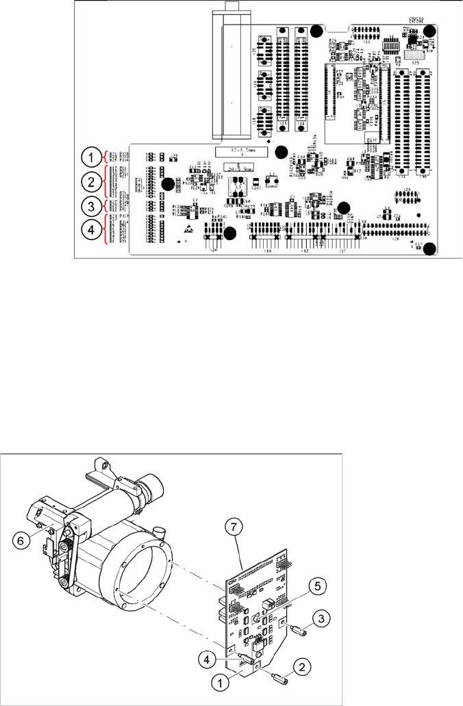
6.3.2.2 LEDs on gantry head distributor
LEDs on gantry head distributor
Legend
Display functions and signals:
1. CAN signal
2. Power supply
3. Head Processor
4. LEDs C&P12
6.3.2.3
6.3.2.3 SP_12 Digital Intermediate Distributor [00330648-05]
SP_12 Digital Intermediate Distributor [00330648-05]
Intermediate distributor
Legend
1. Intermediate distributor
2. Spacer bolt M3x10
3. Spacer bolt M3x10
4. Spacer bolt M3x10
5. Spacer bolt M3x10
6. Front section of C&P head
7. Connectors X1 and X2 (on the rear side)
The intermediate distributor (1) is fixed to the front part (6)
with four spacer bolts (items 2, 3, 4 and 5). The pressure
sensor is located above the spacer bolts (5), on the back
of the intermediate distribution board. The cover of the in-
termediate distributor is fixed with push buttons.
Settings
6.3.2 Boards at C&P12 C&P12
Service Manual SIPLACE D4/D4i 209
The following supply voltages and signals are routed by the intermediate distributor to the individual
placement head modules or to the head board:
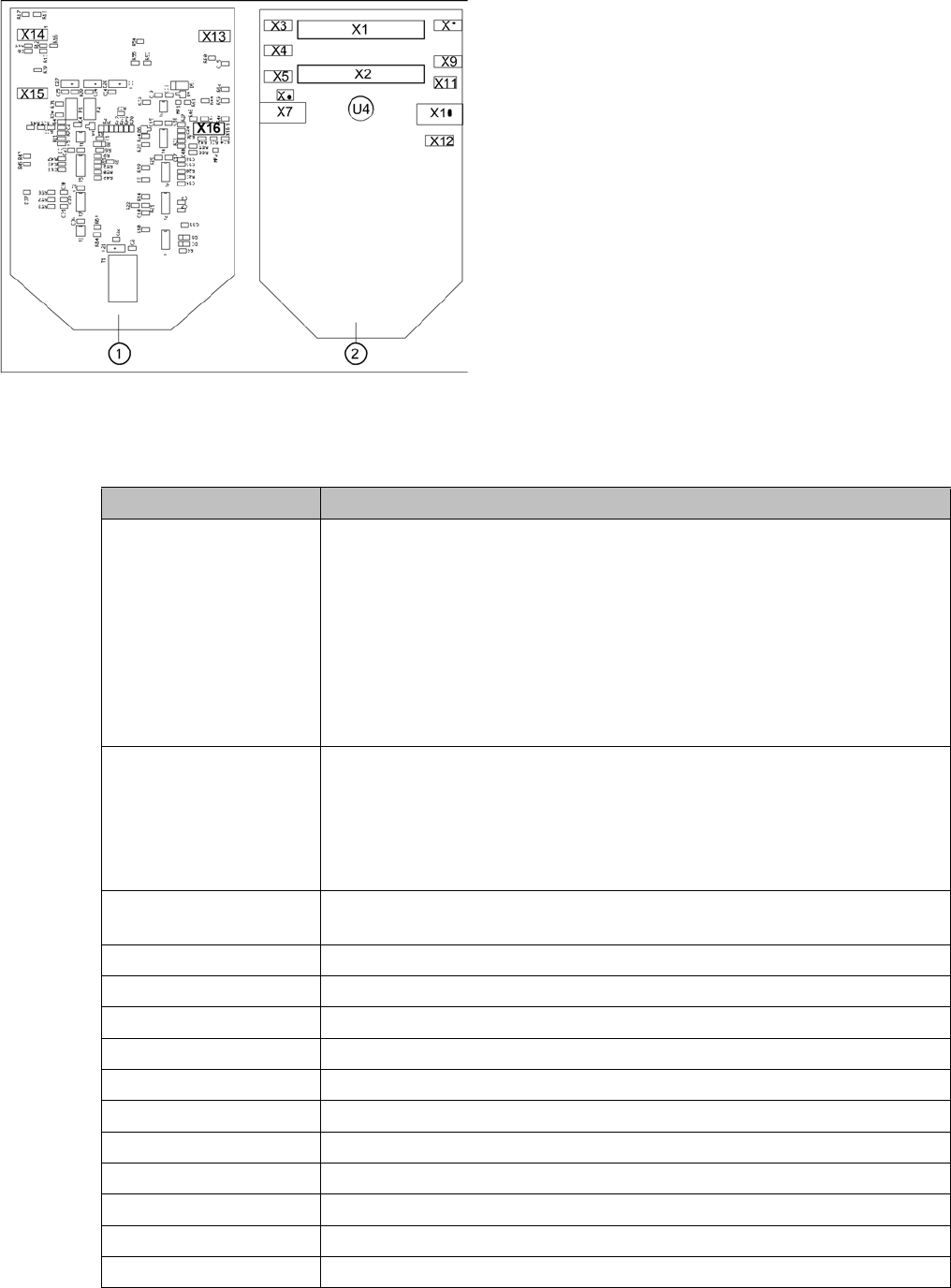
Position of the sockets
Legend
1. Front of the intermediate distributor
2. Back of the intermediate distributor
U4 = pressure sensor
Two 40-pin ribbon cables run from plug X1 and X2 on the
intermediate distributor to socket X14 / X13 on the head
board.
Connectors Description
X1, 40-pole Connected to plug X14 on the head board
▪ Voltage supply, tacho and track signals for the Z axis drive
▪ Signal from light barrier "Z axis in top position"
▪ Signal from light barrier "Z axis in bottom position" (sensor stop signal)
▪ Control signal for the air blast valve
▪ Supply voltage +5 VDC, ±15 VDC
▪ Reference point signal for the DP axis
▪ Track signals for the DP axis
X2, 40-pole Connected to plug X13 of the gantry head distributor
▪ Voltage supply and track signals for the star axis drive
▪ Reference point for the star axis
▪ Analog air blast pressure value
▪ Supply voltages +5 VDC, ±15 VDC, +24 VDC
X3, 10-pole Connection for the Z motor and Z tacho signal (tacho signal is not used on
the HF machine)
X4, 10-pole Connection for the Z axis track signals
X5, 10-pole Connection for the star motor
X6, 6-pole Connection for the air blast valve
X7, 10-pole Connection for the DP axis track signals
X10, 10-pole Connection for the "Z axis up" signal
X11, 8-pole Connection for the light barrier "Z axis down" signal (sensor stop signal)
X12, 10-pole Connection for the star axis track signals
X13, 10-pole Test connection for the Z axis track signals
X14, 10-pole not used
X15, 10-pole Test connection for the star axis track signals
X16, 10-pole Test connection for the DP axis track signals