SIPLACE D4-D4i 工程师手册_EN.pdf - 第122页
Service Work PCB conveyor system 4.4.6 Replacing the Lifting Table Unit [00358653] 122 Service Manual SIPLACE D4/D4i 4.4.6 4 . 4 . 6 R e p la c in g t h e L if t in g T a b le U n it [ 0 0 3 5 8 6 5 3 ] Replacing the Lif…
Service Work
4.4.5 Replacing the Conveyor Toothed Belt [00359917-xx] PCB conveyor system
Service Manual SIPLACE D4/D4i 121
Installation
► Tighten the fastening screws.
► Adjust the belt tension.
4.4.5.1
4.4.5.1 Adjusting the Tension of the Conveyor Toothed Belt
Adjusting the Tension of the Conveyor Toothed Belt
CAUTION! Do not damage the toothed belt!
The toothed belts must not be stretched or kinked!
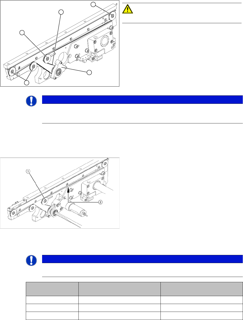
► Feed the new conveyor toothed belt (2) into the drive
unit and weave it round the deflection pulleys (3).
► Insert the tape drive (mount) or drive unit (1) with the
conveyor toothed belt (2) and fasten.
3
3
1
3
2
NOTICE
When replacing the belt on the passive side (tape drive without drive unit), set the track width
to 50 mm. The tape drive must be aligned towards the active side, allowing smooth axial move-
ment of the hexagonal shafts.
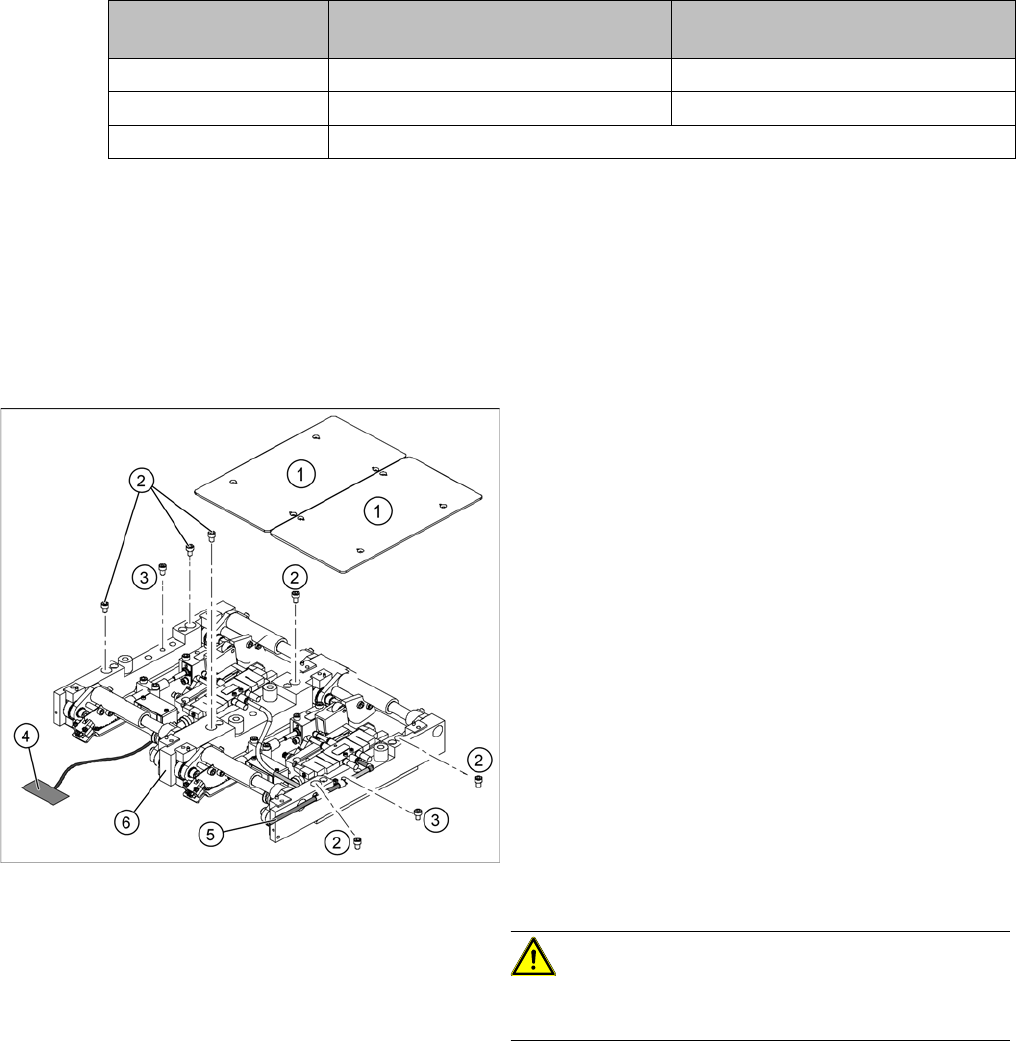
Legend
1. Deflection pulley with slot
2. Measuring point of the belt tension measuring device
(strand center )
► The deflection pulley, around which the conveyor
toothed belt is run, is fastened at a slot. The tension
of the conveyor toothed belt can be adjusted via this
deflection pulley.
► Position the measuring point of the belt tension de-
vice at the strand center (i.e. the longest distance be-
tween the two deflection pulleys) of the conveyor
toothed belt.
► Set the tension of the drive toothed belt according to
the following values.
NOTICE
The tension frequencies per area may vary according to the different belt guides. The belt ten-
sion always remains the same.
Belt tension For conveyor lane 1
(single and dual conveyor)
Conveyor lane 2
(dual conveyor)
Input conveyor 90 Hz +/- 9 Hz 90 Hz +/- 9 Hz
Placement area 1 72 Hz +/- 7 Hz 72 Hz +/- 7 Hz
Intermediate conveyor 144 Hz +/- 14 Hz 115 Hz +/- 12 Hz
Service Work
PCB conveyor system 4.4.6 Replacing the Lifting Table Unit [00358653]
122 Service Manual SIPLACE D4/D4i
4.4.6
4.4.6 Replacing the Lifting Table Unit [00358653]
Replacing the Lifting Table Unit [00358653]
Parts
▪ Lifting table unit for single conveyors [00358653-xx]
▪ Lifting table unit for dual conveyors [00358654-xx]
Removal
Placement area 2 90 Hz +/- 97 Hz 90 Hz +/- 9 Hz
Output conveyor 90 Hz +/- 9 Hz 90 Hz +/- 9 Hz
Width adjustment 24 Hz +/- 2 Hz
Belt tension For conveyor lane 1
(single and dual conveyor)
Conveyor lane 2
(dual conveyor)
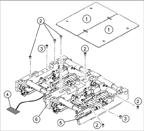
Legend
1. Fastening screws for the lifting table plate
2. 6 x fastening screws for the lifting table
(M8 x 100)
3. 2 x fastening screws for the lifting table
(M6 x 50)
► Move the PCB conveyor to a suitable position from
which you have best access to the lifting table unit.
► Loosen the screw fastening the lifting table plate (1)
and remove the lifting table plate from the lifting table
unit.
► Loosen the screws (2) and (3) fastening the lifting ta-
ble unit.
► Remove the cover on the conveyor conversion board
and unplug the connection cable (4) from the lifting
table unit.
► Unplug the compressed air connection (5).
► Carefully lift the lifting table (6) off the locating pins.
CAUTION! Heavy machine part!
When removing the lifting table, remember it is heavy
(17.5 kg).
Service Work
4.4.6 Replacing the Lifting Table Unit [00358653] PCB conveyor system
Service Manual SIPLACE D4/D4i 123
Installation
See also
6.5.11.1 Adjusting the Speed of the Lifting Table (from SW 602) [ ➙ 239]
► Lift the lifting table unit (6) into the machine and posi-
tion it on the locating pins.
► Screw in the fastening screws (2) and (3).
► Reconnect to the electrical (4) and compressed air
(5) systems.
► Check the lifting table speed and the functionality of
the PCB clamping device, without the lifting table
plate.
► Adjust the speed of the lifting table.
► Carefully place the lifting table plate (1) onto the lifting
table unit and tighten the fastening screws diagonally,
so that the lifting table plate does not stick.
► Check the lifting table speed once the lifting table
plate has been installed.