SIPLACE D4-D4i 工程师手册_EN.pdf - 第135页
Service Work 4.4.16 Replacing the Light Barri er s for Transmitter and Receive r Modules [00370063] PCB conveyor system Service Manual SIPLACE D4/D4i 135 Overview 4.4.16.1 4 . 4 . 1 6 . 1 R e p la c in g t h e T r a n s …
Service Work
PCB conveyor system 4.4.16 Replacing the Light Barriers for Transmitter and Receiver Modules
134 Service Manual SIPLACE D4/D4i
Removal/Installation
4.4.16
4.4.16 Replacing the Light Barriers for Transmitter and Receiver Modules [00370063]
Replacing the Light Barriers for Transmitter and Receiver Modules [00370063]
Parts
Please note the different item numbers for the individual light barriers - these are for the different lengths
of the connection cable.
Please consult the parts catalogue for the individual article numbers.
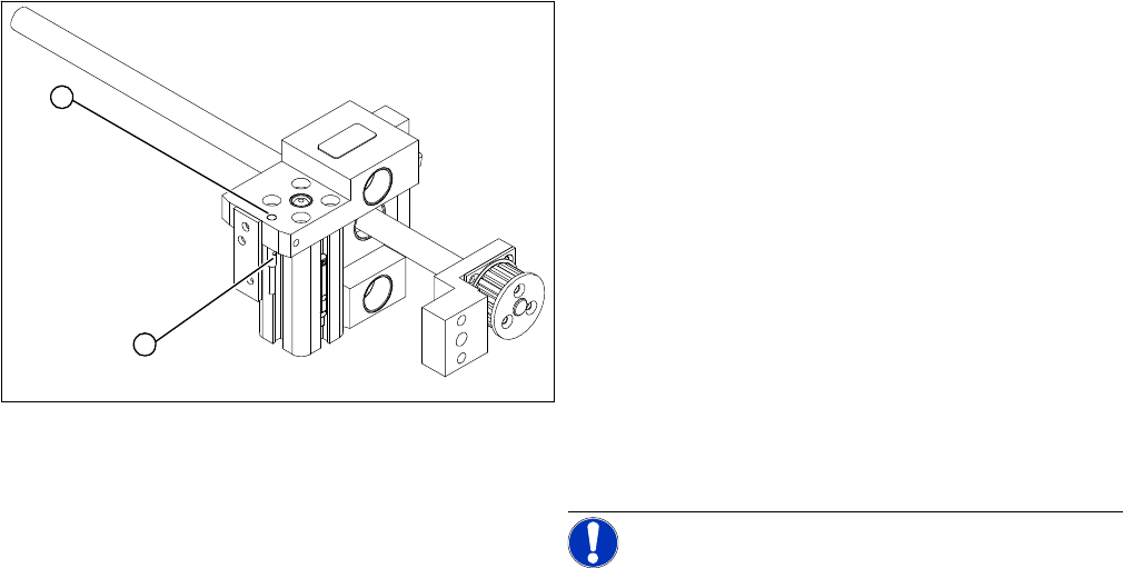
► Loosen the grub screw on the clamping device (1)
and unthread the connection cable as far as the con-
version board of the assembly tub.
► Fit the new proximity switch and reconnect the sys-
tem to the electrical system.
► Fix the proximity switch with the grub screw.
► Tighten the grub screw to a torque of 20 Ncm
(+3 Ncm). The proximity switch must be level with the
adjustment unit housing (2).
► The switching point is set at the actuator on the con-
veyor edge:
► Move the adjustment unit until it is under the convey-
or edge.
► Place a 4/10 mm distance gauge on the adjustment
unit, press the actuator onto the distance gauge and
tighten the screw.
NOTICE! This setting must be performed at all
conveyor edges.
► Use the SITEST program to calibrate the conveyor
edges.
2
1
Service Work
4.4.16 Replacing the Light Barriers for Transmitter and Receiver Modules [00370063] PCB conveyor system
Service Manual SIPLACE D4/D4i 135
Overview
4.4.16.1
4.4.16.1 Replacing the Transmitter or Receiver for Placement Areas 1 + 2
Replacing the Transmitter or Receiver for Placement Areas 1 + 2
Receiver:
► Remove the stop rail.
► Remove the short belt guide.
► Unscrew the holder with the receiver.
► Unscrew the receiver from the holder.
► Unthread the connection cable as far as the relevant conversion board of the conveyor edge.
► Unplug the conversion board of the conveyor edge.
► Rerun the connection cable accordingly and reconnect the conversion board of the conveyor edge
to the electricity supply.
► Fix the receiver at the holder.
► Fix the holder, together with the receiver, to the base so that the holder lies flat on the base.
► Mount the short belt guide and align it.
► Mount the stop rail.
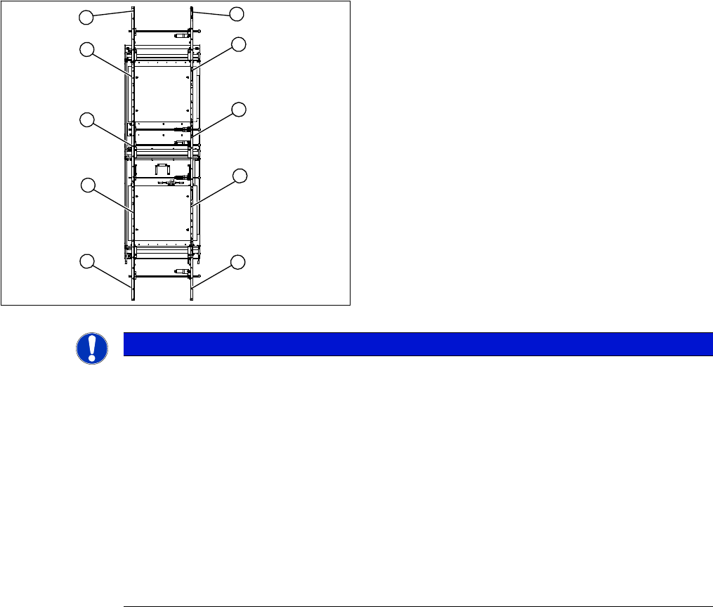
Legend
1. Transmitter at input conveyor
2. Receiver at input conveyor
3. Transmitter at placement area 1
4. Receiver at placement area 1
5. Transmitter at intermediate conveyor
6. Receiver at intermediate conveyor
7. Transmitter at placement area 2
8. Receiver at placement area 2
9. Transmitter at output conveyor
10. Receiver at output conveyor
10
9
8
7
1
6
5
4
3
2
NOTICE
Important instructions for replacing the light barrier
The transmitters are installed on the moveable side of conveyor models, while the receivers are
on the fixed side (applies to the standard conveyor system, fixed side - right).
Check whether it would be helpful to feed in the new cable with the aid of the old one, at least
in some areas.
The connection plug is equipped with contacts, which are pressed onto the wires. You may find
it helpful to remove the contacts from the connection plug, in order to run the cable better
through openings.
For replacement purposes, the connection cable must be unthreaded as far as the relevant
conversion board of the conveyor side. This might be somewhat complicated depending on the
routing of cables inside the machine base.
► You may wish to contact Siemens AG SMD Service regarding this work or proceed as fol-
lows.

Service Work
PCB conveyor system 4.4.16 Replacing the Light Barriers for Transmitter and Receiver Modules
136 Service Manual SIPLACE D4/D4i
Transmitter:
► Unscrew the holder with the receiver.
► Unscrew the receiver from the holder.
► Unthread the connection cable as far as the relevant conversion board of the conveyor edge.
► Unplug the conversion board of the conveyor edge.
► Rerun the connection cable accordingly and reconnect the conversion board of the conveyor edge
to the electricity supply.
► Fix the new light barrier in the original position.
4.4.16.2
4.4.16.2 Replacing the Transmitter or Receiver for the Input or Output Conveyor
Replacing the Transmitter or Receiver for the Input or Output Conveyor
Receiver:
► Remove the stop rail.
► Remove the short belt guide.
► Unscrew the holder with the receiver.
► Unscrew the receiver from the holder.
► Unthread the connection cable as far as the relevant conversion board of the conveyor edge.
► Unplug the conversion board of the conveyor edge.
► Rerun the connection cable accordingly and reconnect the conversion board of the conveyor edge
to the electricity supply.
► Fix the receiver at the holder.
► Fix the holder, together with the receiver, to the base so that the holder lies flat on the base.
► Mount the short belt guide and align it.
► Mount the stop rail.
Transmitter:
► Unscrew the holder with the receiver.
► Unscrew the receiver from the holder.
► Unthread the connection cable as far as the relevant conversion board of the conveyor edge.
► Unplug the conversion board of the conveyor edge.
► Rerun the connection cable accordingly and reconnect the conversion board of the conveyor edge
to the electricity supply.
► Fix the new light barrier in the original position.
NOTICE
Art und Quelle der Gefahr
The transmitters on the input and output conveyors are freely accessible. The bracket must be
loosened and the screws fastening the light barrier removed.
NOTICE
Art und Quelle der Gefahr
Otherwise check whether you can run the cable through the opening by removing the contacts
in the connection plug.