SIPLACE D4-D4i 工程师手册_EN.pdf - 第123页
Service Work 4.4.6 Replacing the Lifting Table Unit [00358653] PCB conveyor system Service Manual SIPLACE D4/D4i 123 Installation See also 6.5.11.1 Adjusting the Speed of the Lifting Table (from SW 602) [ ➙ 239] ► Li…
Service Work
PCB conveyor system 4.4.6 Replacing the Lifting Table Unit [00358653]
122 Service Manual SIPLACE D4/D4i
4.4.6
4.4.6 Replacing the Lifting Table Unit [00358653]
Replacing the Lifting Table Unit [00358653]
Parts
▪ Lifting table unit for single conveyors [00358653-xx]
▪ Lifting table unit for dual conveyors [00358654-xx]
Removal
Placement area 2 90 Hz +/- 97 Hz 90 Hz +/- 9 Hz
Output conveyor 90 Hz +/- 9 Hz 90 Hz +/- 9 Hz
Width adjustment 24 Hz +/- 2 Hz
Belt tension For conveyor lane 1
(single and dual conveyor)
Conveyor lane 2
(dual conveyor)
Legend
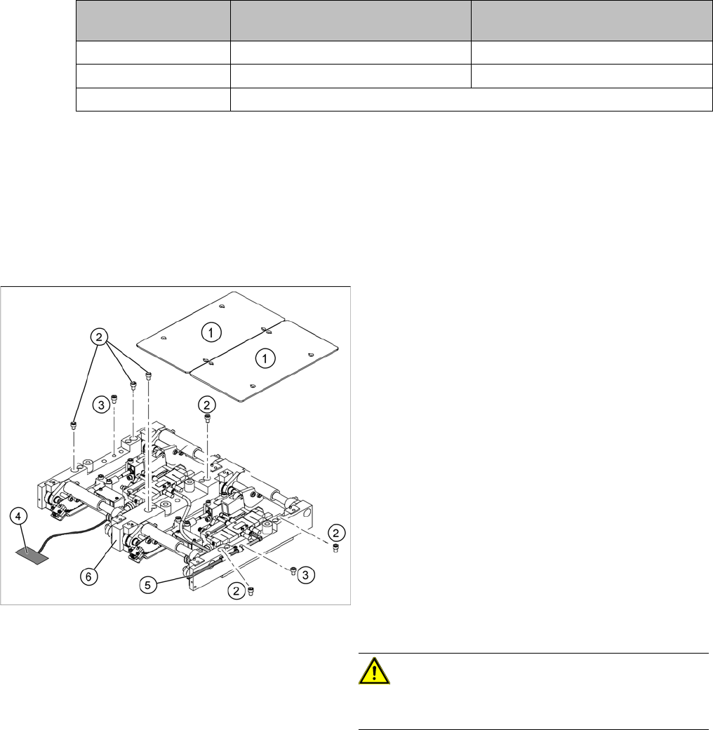
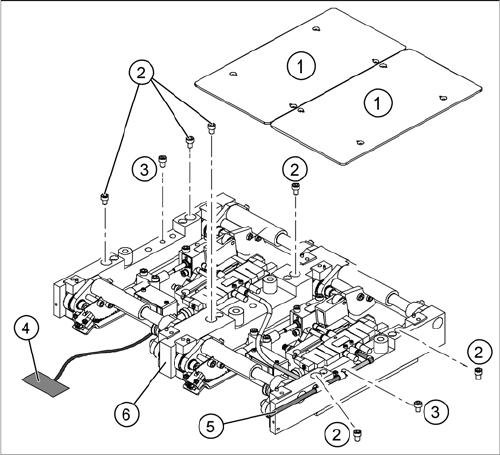
1. Fastening screws for the lifting table plate
2. 6 x fastening screws for the lifting table
(M8 x 100)
3. 2 x fastening screws for the lifting table
(M6 x 50)
► Move the PCB conveyor to a suitable position from
which you have best access to the lifting table unit.
► Loosen the screw fastening the lifting table plate (1)
and remove the lifting table plate from the lifting table
unit.
► Loosen the screws (2) and (3) fastening the lifting ta-
ble unit.
► Remove the cover on the conveyor conversion board
and unplug the connection cable (4) from the lifting
table unit.
► Unplug the compressed air connection (5).
► Carefully lift the lifting table (6) off the locating pins.
CAUTION! Heavy machine part!
When removing the lifting table, remember it is heavy
(17.5 kg).
Service Work
4.4.6 Replacing the Lifting Table Unit [00358653] PCB conveyor system
Service Manual SIPLACE D4/D4i 123
Installation
See also
6.5.11.1 Adjusting the Speed of the Lifting Table (from SW 602) [ ➙ 239]
► Lift the lifting table unit (6) into the machine and posi-
tion it on the locating pins.
► Screw in the fastening screws (2) and (3).
► Reconnect to the electrical (4) and compressed air
(5) systems.
► Check the lifting table speed and the functionality of
the PCB clamping device, without the lifting table
plate.
► Adjust the speed of the lifting table.
► Carefully place the lifting table plate (1) onto the lifting
table unit and tighten the fastening screws diagonally,
so that the lifting table plate does not stick.
► Check the lifting table speed once the lifting table
plate has been installed.
Service Work
PCB conveyor system 4.4.7 Replacing the Lifting Table Solenoid Valve [00358663]
124 Service Manual SIPLACE D4/D4i
4.4.7
4.4.7 Replacing the Lifting Table Solenoid Valve [00358663]
Replacing the Lifting Table Solenoid Valve [00358663]
Removal/Installation
4.4.8
4.4.8 Replacing the Lifting Table Fork Light Barrier [00363079]
Replacing the Lifting Table Fork Light Barrier [00363079]
Parts
▪ Light barrier for track A – dual conveyor [00363079-xx]
▪ Light barrier for track B – dual conveyor [00363080-xx]
▪ Light barrier for track A – single conveyor [00363111-xx]
▪ Light barrier for track B – single conveyor [00363113-xx]
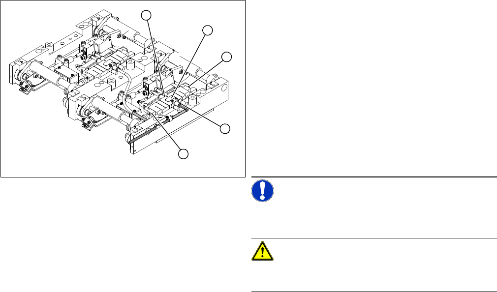
Legend
1. Solenoid valve with 2 x fastening screws
2. Connection plug
3. Compressed air connections
► Move the PCB conveyor to the position which gives
you best access to the lifting table.
► Move the Y gantries into the area outside the PCB
conveyor.
► Switch off the machine and secure it to prevent unau-
thorized reactivation.
► Loosen the screw fastening the lifting table plate and
remove the lifting table plate from the lifting table unit.
NOTICE! You may wish to completely dismantle
the lifting table, to give you better access to the solenoid
valves.
CAUTION! Heavy machine part!
When removing the lifting table, remember it is heavy
(17.5 kg).
► Switch off the compressed air supply and release the
air at the pneumatic unit filter.
► Loosen the screws fastening the connection plug and
then unplug it.
► Remove the compressed air connections.
► Fit the new solenoid valve and reconnect the electri-
cal and compressed air systems.
► Fit the complete lifting table into the machine again.
► Check the speed of the lifting table and correct where
necessary.
3
2
1
3
2