SIPLACE D4-D4i 工程师手册_EN.pdf - 第223页
Settings 6.4.3 Check the gap between the empty-tape baffle, inside and t he leading edge of the tape deflector. Component Handling Service Manual SIPLACE D4/D4i 223 The jumper for the CAN b us addressing must b e set acc…
Settings
Component Handling 6.4.2 Control Unit on Cutter
222 Service Manual SIPLACE D4/D4i
6.4.1.3
6.4.1.3 Adjusting the Component Trolley Height
Adjusting the Component Trolley Height
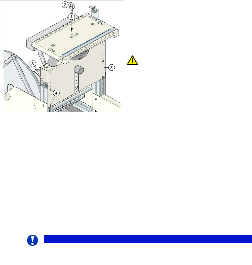
Overview
Setting
► Remove all the feeder modules from the component trolley.
► Screw the eyebolt into the M12 hole provided (1) on the component trolley table.
► Hook the leverage device into the eyebolt (2).
► Tighten the rope of the leverage device.
► Loosen the 8 hexagon socket-head screws, M6x12 (4).
► Lift or lower the component trolley table to the required height. Make sure that the hole for the re-
quired height in the bridge (5) is level with the top hole in the vertical profile bar (3).
► Fasten the bridge (5) to the vertical profile bar (3) with the eight hexagon socket-head screws M6x12
(4).
► Unscrew the eyebolt from the component trolley table.
6.4.2
6.4.2 Control Unit on Cutter
Control Unit on Cutter
Position of eyebolt on component trolley
1. M12 hole drilled for eyebolt
2. Eyebolt DIN 580 M12-St
3. Vertical profile bar
4. Eight pieces hexagon socket-head screw SN 62355,
M6x12
5. Bridge
CAUTION!
Always use the fit-up aid (screwed eyelet) to fix the table
plate, irrespective of whether you want to raise or lower
the component trolley.
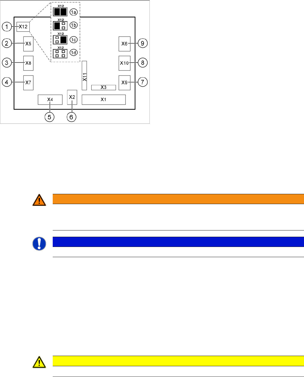
NOTICE
Control unit [03006411-xx] is replaced by CAN node module.
This version of the control unit is replaced by the backwards compatible CAN node [03052027-
xx] module.
Settings
6.4.3 Check the gap between the empty-tape baffle, inside and the leading edge of the tape deflector. Component Handling
Service Manual SIPLACE D4/D4i 223
The jumper for the CAN bus addressing must be set according to the corresponding location in the ma-
chine.
6.4.3
6.4.3 Check the gap between the empty-tape baffle, inside and the leading edge of the tape deflector.
Check the gap between the empty-tape baffle, inside and the leading edge of the tape
deflector.
► With the feeler gauge, check:
The distance between the empty-tape baffle and the leading edge of the tape deflector must again
be within the TARGET distance 1.0 to 1.5 mm over the entire length.
If the gap is not OK.
► Loosen the screws holding the empty-tape duct once again and correct the position of the duct in the
holes.
► If this is not enough, you may assume that the cutter was already not in the optimal position before
the empty-tape duct was replaced:
In this case, correct the position of the cutter in the holes of the retaining brackets as described in
"4.3.2.5 Exchanging the Pneumatic Cutter" [ ➙ 83].
► Perform the appropriate “Final Steps”.
See also
4.3.2.4.1 Tightening Torques for Cutter Screws [ ➙ 83]
4.3.2.14 Final Steps [ ➙ 107]
Jumper setting on the tape cutter unit (example of D4/D4i
shown)
1. X12 – Jumper for location encoding for cutter:
1a: gantry 1
1b: gantry 2
1c: gantry 3
1d: gantry 4
2. X5 – Voltage supply to valve (left)
3. X8 – Proximity switch for stroke cylinder out (left)
4. X7 – Proximity switch for stroke cylinder in (left)
5. X4 – CAN bus connection
6. X2 – Voltage supply for cutter +24 V and +5 V
7. X9 – Proximity switch for stroke cylinder in (left)
8. X10 – Proximity switch for stroke cylinder out (right)
9. X6 – Voltage supply to valve (right)
WARNING
The following check can only be conducted from the bottom of the cutter after it has been in-
stalled in the machine. Wear thick protective gloves;
there is a risk of injury from the blades and the edge of the tape deflector.
NOTICE
For the adjustments it is the best, if a second person is available
CAUTION
► Tighten the screws to the correct torque.
Settings
Conveyor 6.5.1 Adjusting the Tension of the Conveyor Toothed Belt
224 Service Manual SIPLACE D4/D4i
6.5
6.5 Conveyor
Conveyor
6.5.1
6.5.1 Adjusting the Tension of the Conveyor Toothed Belt
Adjusting the Tension of the Conveyor Toothed Belt
NOTICE
Measuring at strand center
The belt tension is measured at the strand center (i.e. the longest distance between the two
deflection pulleys).
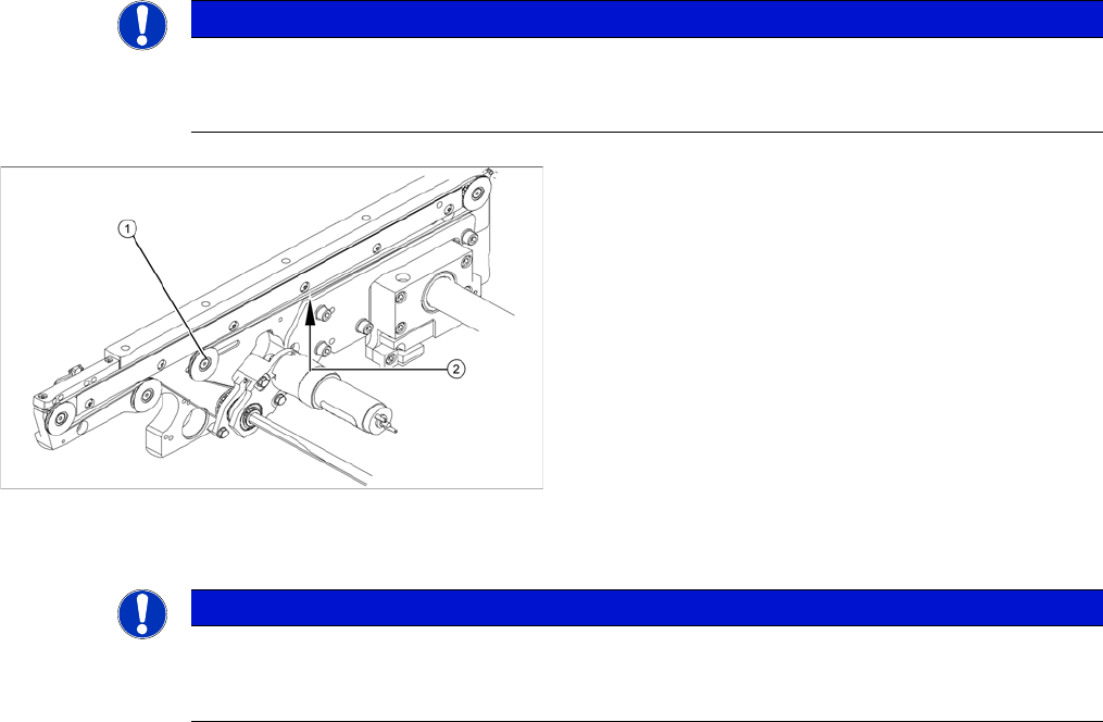
Measuring and setting the tension of the conveyor
toothed belt
1. Deflection pulley with slot
2. Measuring point of the belt tension measuring device
► Each conveyor section contains a deflection pulley
(1), that can be moved. The tension of the conveyor
toothed belt can be adjusted by moving this deflection
pulley.
► Position the measuring point of the belt tension de-
vice at the strand center (i.e. the longest distance be-
tween the two deflection pulleys) of the conveyor
toothed belt.
► Set the tension of the conveyor toothed belt accord-
ing to the following values.
NOTICE
Different frequencies
The tension frequencies per area may vary according to the different belt guides. The belt ten-
sion always remains the same.