SIPLACE D4-D4i 工程师手册_EN.pdf - 第186页
Service Work C&P12 Placement Head 4.5.25 Replac ing the Vacuum Hoses on the C& P Head 186 Service Manual SIPLACE D4/D4i Removal ► Loosen the old membrane with an Allen key ( 1.5 mm) and remove th e membrane. Inst…
Service Work
4.5.23 Replacing the Raceway (Circular Arc Guide) C&P12 Placement Head
Service Manual SIPLACE D4/D4i 185
4.5.23
4.5.23 Replacing the Raceway (Circular Arc Guide)
Replacing the Raceway (Circular Arc Guide)
4.5.24
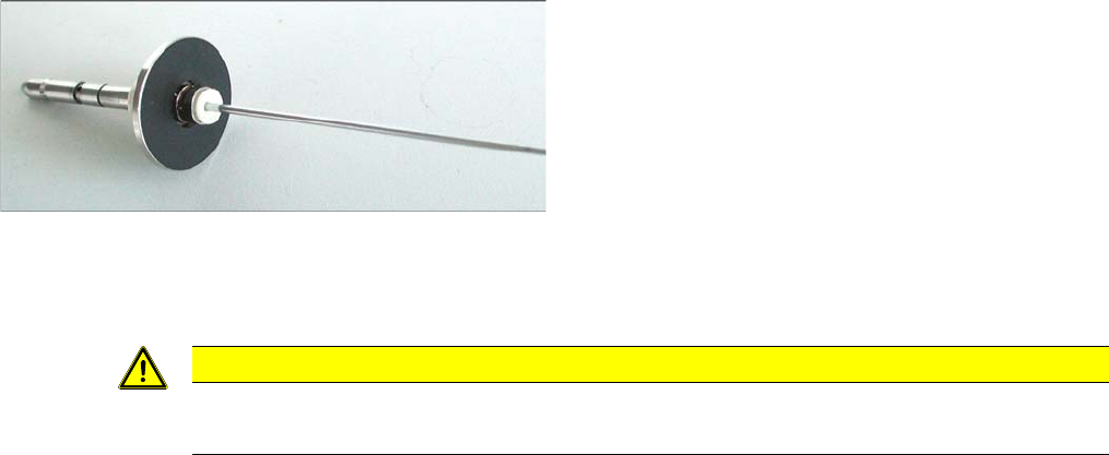
4.5.24 Replacing the Membrane (Vacuum Plate) on the Sleeve [03037984-xx]
Replacing the Membrane (Vacuum Plate) on the Sleeve [03037984-xx]
The sealing membrane on the sleeves ensures sufficient vacuum by sealing the tip of the nozzle (serves
as the air inlet) in the sleeve.
Tools and equipment
▪ Standard tool
▪ Spare part: membrane (vacuum plate) [03037984-xx]
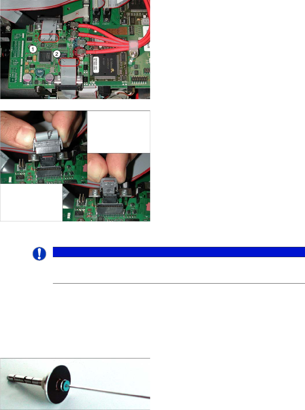
The adjacent diagram shows the press-fit connections for
the component camera (1) and the PCB camera (2) on
the Vision board of the SIPLACE D1/D2. Each of the two
positions has two connectors of different sizes with fixture
clips.
➢ To release the press-fit connections, press the con-
nector sides together at the top, with your thumb and
index finger.
► The fixture clips will open and the connector can be
pulled up and off.
⇨ The adjacent diagram shows the two press-fit con-
nections arranged one above the other, for the
Vision
signals
(small connector) and
illumination control
(large connector) after disconnection of the connec-
tors.
NOTICE
SIPLACE Service
This service task may only be performed by specially trained SIPLACE service technicians. The
procedure is described in a separate manual.
Blue membrane for the sleeve with ball fixing C&P6/12
(old version [00354244-xx])
Service Work
C&P12 Placement Head 4.5.25 Replacing the Vacuum Hoses on the C&P Head
186 Service Manual SIPLACE D4/D4i
Removal
► Loosen the old membrane with an Allen key (1.5 mm) and remove the membrane.
Installation
► Fit the new membrane onto the sleeve and tighten the membrane with an Allen key.
4.5.25
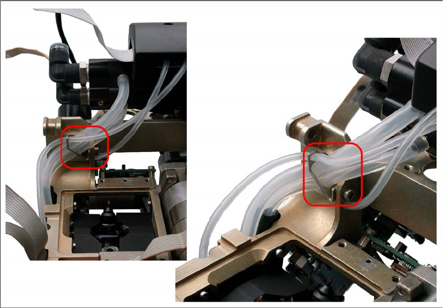
4.5.25 Replacing the Vacuum Hoses on the C&P Head
Replacing the Vacuum Hoses on the C&P Head
The length of the vacuum hoses and the way in which they are fitted has been improved to ensure that,
when the hoses are replaced - especially in SX, DX, X, D3 and HF machines - these hoses can be run
in a manner which will not interrupt the vacuum supply.
Tools and equipment
▪ Standard tool
▪ Spare part: vacuum hoses and guidance [03064147-xx]
Contents:
– Hose for placement circuit query (new length: 180 mm, old length: 190 mm) [03002187-02]
– Hose for holding circuit query (new length: 225 mm, old length: 200 mm) [03002188-02]
– Hose for placement circuit / 3x6x145 (new length: 145 mm, old length: 125 mm) [03010444-02]
– Hose for hold circuit / 4x7x140 [03010445S01]
– Hose guide [03048807-01]
– Cylinder screw M3x6 DIN912-A2 [03045028-01]
White membrane for the sleeve with ball fixing C&P6/12,
made of an alternative material
(new version [03037984-xx])
CAUTION
Do not use a ball Allen key!
► Make sure that you do not use a ball Allen key.
Service Work
4.5.25 Replacing the Vacuum Hoses on the C&P Head C&P12 Placement Head
Service Manual SIPLACE D4/D4i 187
Removal/installation
► Mark the connection points and the route of the individual hoses, so that these can be rerun correctly
later on.
► Disconnect the hoses from the vacuum generator and the vacuum measuring board.
► Fit the additional hose guide (M3 screw) on the top measuring hose duct.
► Fit the new hose as shown in the diagrams.