SIPLACE D4-D4i 工程师手册_EN.pdf - 第96页
Service Work Component Handling 4.3.2 Cutter 96 Service Manual SIPLACE D4/D4i 4.3.2.8 4 . 3 . 2 . 8 R e p la c in g t h e A r t ic u la t e d J o in t o n t h e S h o r t - S t r o k e C y lin d e r [ 0 0 3 4 8 5 7 9 - x…
Service Work
4.3.2 Cutter Component Handling
Service Manual SIPLACE D4/D4i 95
See also
4.3.2.7 Replacing the Stationary Blade and Movable Blade incl. Spacers [ ➙ 91]
4.3.2.4.1 Tightening Torques for Cutter Screws [ ➙ 83]
6.4.3 Check the gap between the empty-tape baffle, inside and the leading edge of the tape deflec-
tor. [ ➙ 223]
4.3.2.14 Final Steps [ ➙ 107]
► Make certain that the edges are parallel, then screw
the cover plate holder to the cutter (two M4 screws
each (7, 9)):
⇨ -> Do not pinch or put strain on the cables.
► Install the cover plate on the stationary blade (4 M4
screws (12, 13)).
► Remove the parallel clamps from the cutter or dis-
mantle the cutter from the mounting plate.
► Fit the cutter back into the machine. (See "4.3.2.5 Ex-
changing the Pneumatic Cutter" [ ➙ 83].)
► Fit the empty-tape duct assembly and check the gap
between the empty-tape baffle, inside and the leading
edge of the tape deflector.
► Perform the appropriate “Final Steps”.
Service Work
Component Handling 4.3.2 Cutter
96 Service Manual SIPLACE D4/D4i
4.3.2.8
4.3.2.8 Replacing the Articulated Joint on the Short-Stroke Cylinder [00348579-xx]
Replacing the Articulated Joint on the Short-Stroke Cylinder [00348579-xx]
Removing the articulated joint and short-stroke cylinder
► Remove the cutter from the machine. (See "4.3.2.5 Exchanging the Pneumatic Cutter" [ ➙ 83].)
► Remove the deflector plate from the cutter.
► Loosen the screws holding the moveable blade.
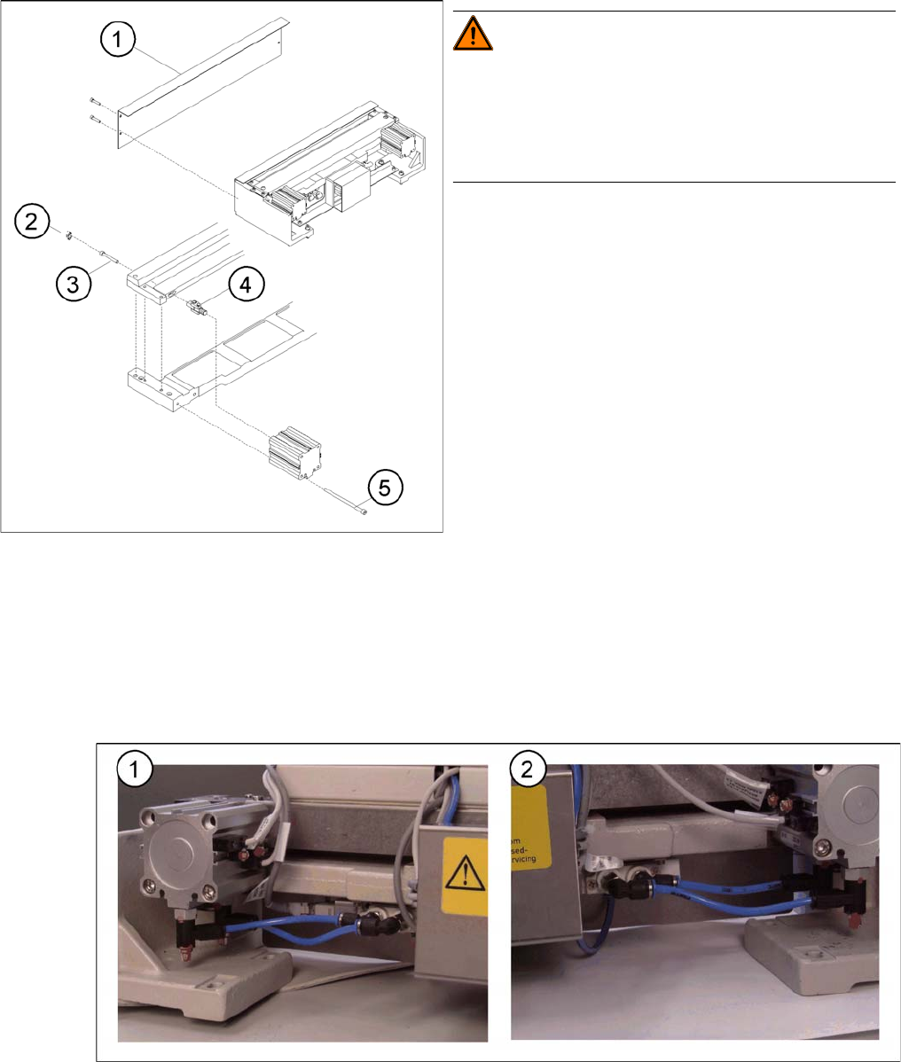
Compressed air connections, left (1) and right (2)
► Loosen the compressed air connections (1, 2) on the short-stroke cylinder.
► In addition, mark the allocation of the proximity switches to the short-stroke cylinder (position front/
back).
Replacing the articulated joint on the short-stroke cylin
-
der
WARNING! Risk of injury!
Wear appropriately thick protective gloves!
There is a high risk of injury from the blades and the tape
deflector.
Never reach into the cutter from below or into the empty-
tape duct from above.
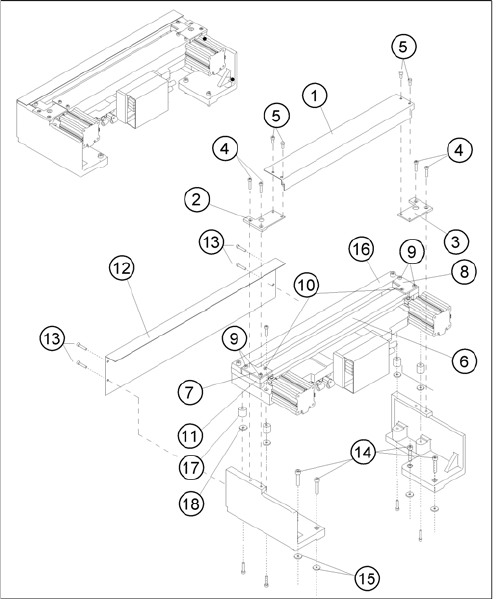
Legend
1. Deflector plate
2. Cover
3. Screws to fasten short-stroke cylinder
4. Articulated joint
5. Screws to fasten the moveable blade
Service Work
4.3.2 Cutter Component Handling
Service Manual SIPLACE D4/D4i 97
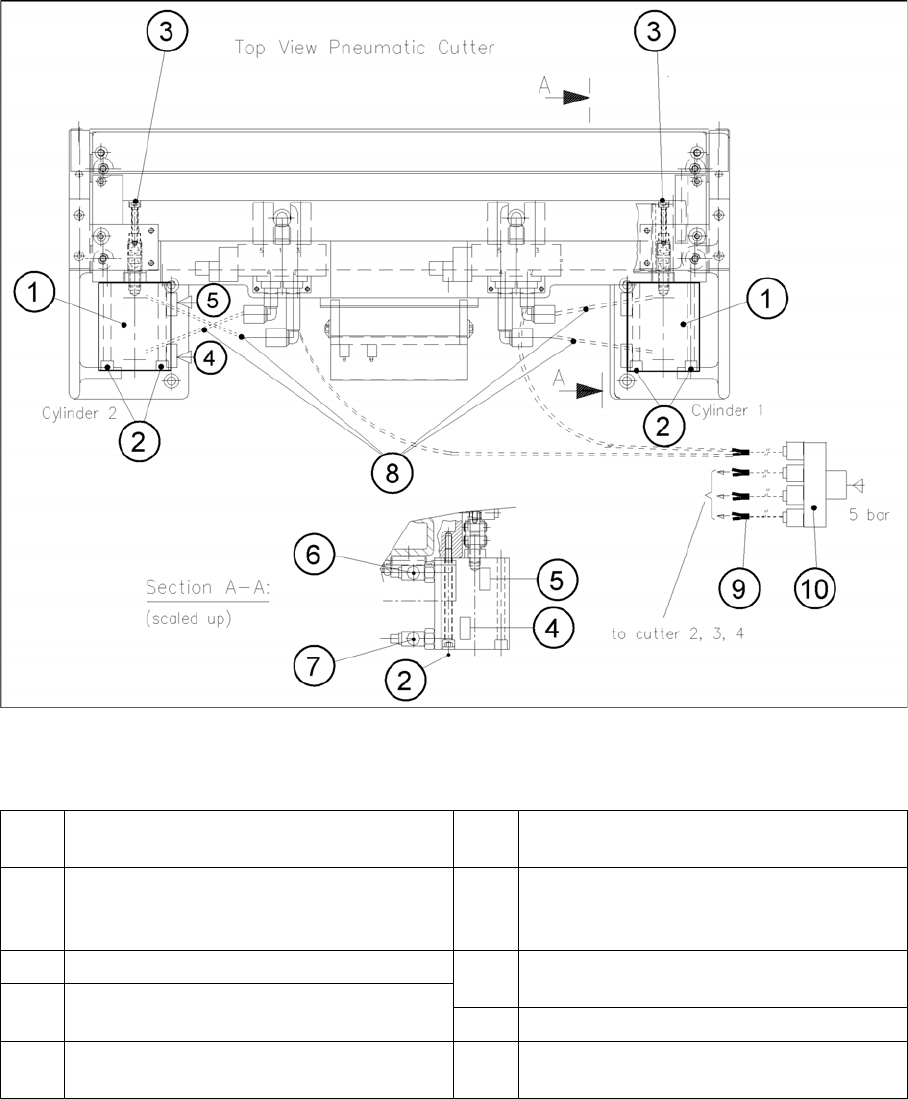
Removing and Installing the Short-Stroke Cylinder
Legend
► Loosen the screws fastening the two inductive proximity switches to the short-stroke cylinder (1
screw each (4, 5)).
► Loosen the screws fastening the short-stroke cylinder (1) (2 M5x65 screws (5)) and remove the cyl-
inder, incl. the articulated joint screwed into it.
1 Short-stroke cylinders 1 and 2 6 One-way restrictor (for running cylinder
out)
2 Screws fastening the short-stroke cylin-
ders: 2 M 5x65 hexagon socket-head
screws each
7 One-way restrictor (for running cylinder in)
3 Articulated joint fixtures 8 Allocation of the compressed air connec-
tions, pneumatic hoses
4 Proximity switch (for position cylinder
moved in). Fastener: 1 Phillips screw 9 Y-socket union (in the cable duct)
5 Proximity switch (for position cylinder
moved out). Fastener: 1 Phillips screw
10 Multiple-Y-distributor on the safety valve (5
bar from compressed air unit)