SIPLACE D4-D4i 工程师手册_EN.pdf - 第52页
Service Work Electrical System 4.1.2 Measuring the Power Supply Unit 52 Service Manual SIPLACE D4/D4i F1 Fuse unit 3 x 230V/400V AC 115 VAC / 130 VAC / 220 VAC SZ2 SZ3 SZ23 Auxiliary contactors U,V,W for X/Y servos 3 x 1…
Service Work
4.1.2 Measuring the Power Supply Unit Electrical System
Service Manual SIPLACE D4/D4i 51
4.1.2.1
4.1.2.1 Front View
Front View
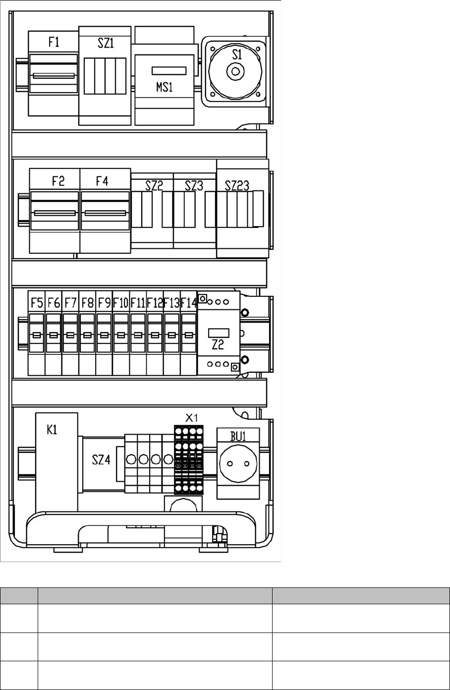
Power supply unit - front panel - parts overview
Item Designation Voltages
S1 Main switch 3LC4/3-pole/40A 3 x 204 V~ / 3 x 230 V~ / 3 x 380 V~
/ 3 x 400 V~ / 3 x 415 V~
MS1 Motor circuit-breaker PKZ2/3-pole/40A 3 x 204 V~ / 3 x 230 V~ / 3 x 380 V~
/ 3 x 400 V~ / 3 x 415 V~
SZ1 Contactor 3RT10/24VDC/size S2 3 x 204 V~ / 3 x 230 V~ / 3 x 380 V~
/ 3 x 400 V~ / 3 x 415 V~

Service Work
Electrical System 4.1.2 Measuring the Power Supply Unit
52 Service Manual SIPLACE D4/D4i
F1 Fuse unit 3 x 230V/400V AC 115 VAC / 130 VAC / 220 VAC
SZ2
SZ3
SZ23 Auxiliary contactors U,V,W for X/Y servos 3 x 140 VAC
F4 Fuse unit - X/Y axes 3 x 200 VAC
F2 Fuse unit 230VAC for 5V power supply 3 x 220 VAC
Z2 Reactor
F14 24 V DC board conveyor and monitors 24 VDC against ground
F13 24 V DC Box PC, axis unit (fan) 24 VDC against ground
F12 24 V DC internal power supply, Micro Box PC 24 VDC against ground
F11 24 V DC sector distributor 24 VDC against ground
F10 48 V DC Vision illumination, DC/DC converter 48 VDC against ground
F9 8 V DC changeover table 8 VDC against ground
F8 40 V DC PCB handling (conveyor) 40 VDC against ground
F7 40 V DC changeover table 40 VDC against ground
F6 40 V DC/DP axes (servo card) 40 VDC against ground
F5 150V DC star axis (servo card) 150 VDC against ground
BU1 Service socket 115 / 130 / 220 / 230 / 240 VAC
X1 Feed in - terminal strip 3 x 204 V~ / 3 x 230 V~ / 3 x 380 V~
/ 3 x 400 V~ / 3 x 415 V~
FBU Fuse 6.3 AT 1 x 220 V~ against ground
FW Fuse 6.3 AT 1 x 220 V~ against ground
FV Fuse 6.3 AT 1 x 220 V~ against ground
fu Fuse 6.3 AT 1 x 220 V~ against ground
SZ4 Contactor control "ON software" 24 VDC
R1 Relay control "ON button"
K1 Protective contactor combination (PCC) 24 VDC against ground
Item Designation Voltages
Service Work
4.1.2 Measuring the Power Supply Unit Electrical System
Service Manual SIPLACE D4/D4i 53
4.1.2.2
4.1.2.2 Side View
Side View
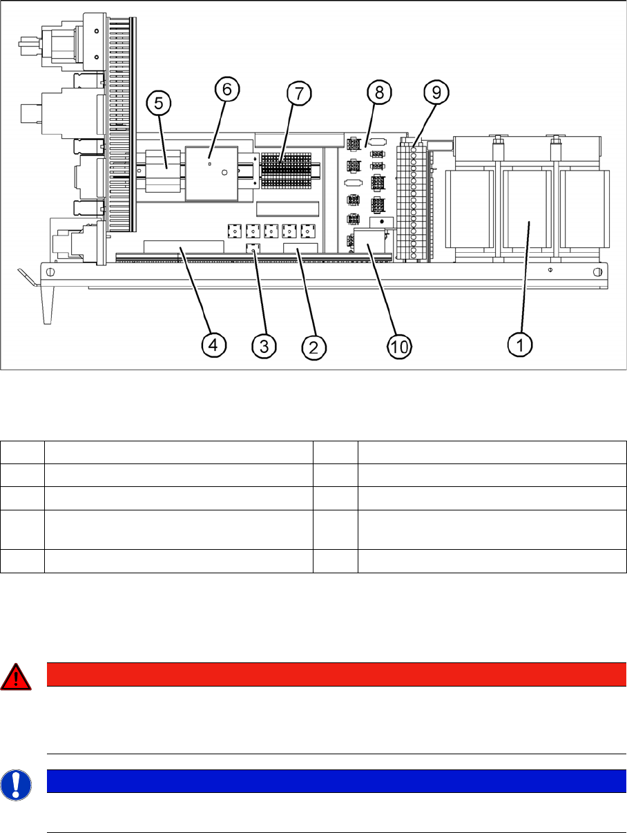
Power supply - side view - parts overview
Legend
Measuring voltages at rectifiers V1 to V8
The diagram above shows the position of rectifiers V1 to V7.
To measure the rectifiers V1 and V7, first remove the perspex panel.
1 T1 transformer 11.1 kVA 6 A 3 power fail board
2 V1 rectifier 7 Terminal strip X1
3 V2-V7 rectifier S101-B6U 160-08 8 Connector strip X2 to X10, X12, X13
4 Z1 line filter - input voltage 9 Secondary terminal strip with fuses (output
voltage T1)
5 A2 current supply (5V/6.3A) 10 Electrolytic capacitor C1
DANGER
RISK OF DEATH BY ELECTRIC SHOCK
► Switch the placement system off at the main switch.
► Disconnect the placement system from the power supply.
NOTICE
The placement system must have started, otherwise there will be no AC voltage (3 x 140 VAC)
at rectifier V1.