SIPLACE D4-D4i 工程师手册_EN.pdf - 第202页
Settings Gantry 6.2.3 Description of the PCB boards on the Gantry 202 Service Manual SIPLACE D4/D4i Gantry head distri butor (from bel ow) Legend See also 6.3.2.1 8-fold DIP Switch of the ga ntry head dist ributor (i…
Settings
6.2.3 Description of the PCB boards on the Gantry Gantry
Service Manual SIPLACE D4/D4i 201
6.2.3.1
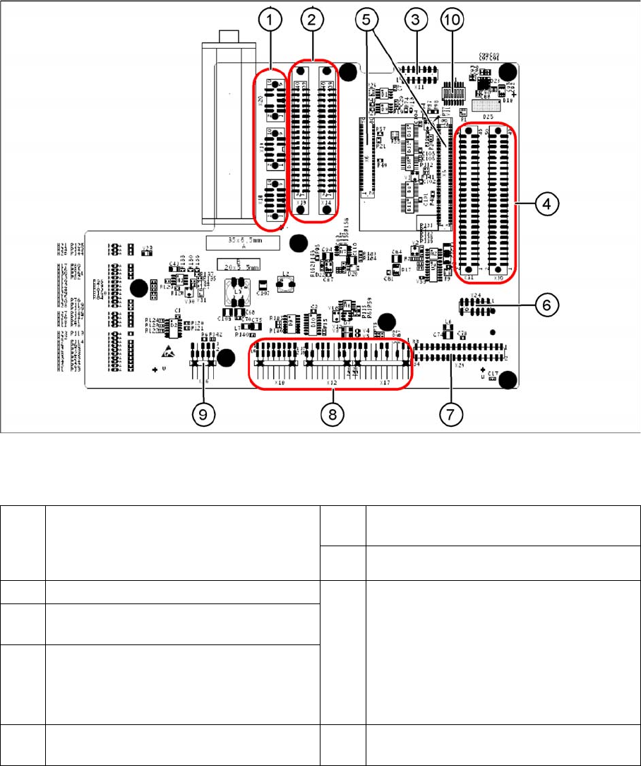
6.2.3.1 Gantry Head Distributor
Gantry Head Distributor
Gantry head distributor (from above)
Legend
1 X20 stepping motor for reject position
X19 stepping motor for pickup/place
X18 stepping motor for swiveling in the DP
axis
6 X24 Test connector for „digital track signals
for X-axis“
7 X29 connector for Vision board
2 X13/X14 flat ribbon cable to C&P head 8 X10 Connector vacuum measurement
board
X12 DP axis motor
X16 Reference proximity switch (nor used)
X17 X-axis end position proximity switch
(not used)
X22 Temperature feeler
X21 Free (not used)
3 X11 test connector for CAN Bus, SPI Bus,
RS232
4 X30/X31 flat ribbon cable to P&P head for
D1/D1i (D4/D4i not in use)
5 X5/X6 connector for 16 bit processor
(TQM)
9 X26 connector for CO sensor
Settings
Gantry 6.2.3 Description of the PCB boards on the Gantry
202 Service Manual SIPLACE D4/D4i
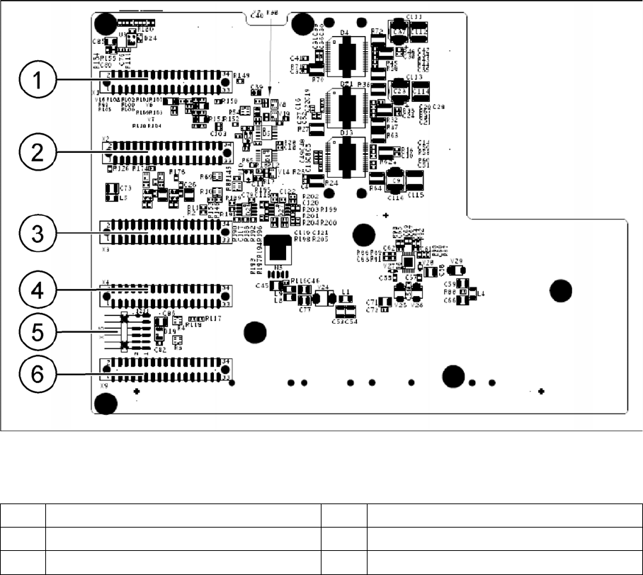
Gantry head distributor (from below)
Legend
See also
6.3.2.1 8-fold DIP Switch of the gantry head distributor (incl. switch S1) – C&P6/12 [ ➙ 207]
6.2.4.1 DIP Switch on Gantry Head Distributor [ ➙ 205]
1 X1 flat ribbon cable 4 X4 not connected
2 X2 flat ribbon cable 5 X15 connector for X-axis track signals
3 X3 flat ribbon cable 6 X9 flat ribbon cable
Settings
6.2.3 Description of the PCB boards on the Gantry Gantry
Service Manual SIPLACE D4/D4i 203
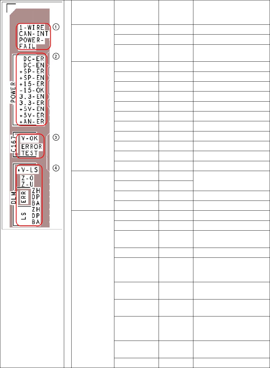
Description of LEDs on the Gantry Head Distributor
SM = stepping motor
Legend PCB labeling LEDS for
oeprating
states
Description
1
CAN Bus
1-WIRE Not in use
CAN-INT OFF not used
POWER-FAIL OFF Error +24 V power supply
(from the main machine)
2
Status voltage
supplies
DC-ER OFF Error DC/DC converter
DC-EN ON Enable DC/DC converter
+SP-ER OFF Error +5V track encoder
+SP-EN ON Enable +5V track encoder
+15-ER OFF Error +15V
-15-OK ON -15V is OK
3.3-EN ON Enable +3.3V digital
3.3-ER OFF Error +3.3V digital
+5V-EN ON Enable +5 V digital
+5V-ER OFF Error +5V digital
+AN-ER OFF Error analog supply C167
3
Head CAN
processor
V-OK ON Internal voltage monitoring
of eSW
V-OK OFF
ERROR OFF Error eSW
TEST Flashing Timer eSW in operation
4
C&P head
functions and
signals
+V-LS ON OK + 15V light barrier
+V-LS OFF Error +15V light barrier
Z-O ON Z axis is not up (in fork light
barrier)
Z-U ON Z down has switched
ERR-ZH OFF Overload SM valve position-
ing drive for pickup and
place
ERR-DP OFF Overload SM swivel in DP
axis
ERR-BA OFF Overload SM valve position-
ing drive for reject
LS-ZH ON Light barrier SM valve posi-
tioning drive for pickup and
place
LS-DP ON Light barrier SM for swivel in
DP axis
LS-BA ON Light barrier SM reject