SIPLACE D4-D4i 工程师手册_EN.pdf - 第138页
Service Work PCB conveyor system 4.4.17 Replac ing the Laser Light Barriers fo r Stopper Positions [00370385] 138 Service Manual SIPLACE D4/D4i Overview Removal/Installation of transmitter module assembly Legend 1. Trans…

Service Work
4.4.17 Replacing the Laser Light Barriers for Stopper Positions [00370385] PCB conveyor system
Service Manual SIPLACE D4/D4i 137
4.4.16.3
4.4.16.3 Replacing the Light Barriers for the Intermediate Conveyor
Replacing the Light Barriers for the Intermediate Conveyor
Transmitter:
► Unscrew the holder with the receiver.
► Unscrew the receiver from the holder.
► Unthread the connection cable as far as the relevant conversion board of the conveyor edge.
► Unplug the conversion board of the conveyor edge.
► Rerun the connection cable accordingly and reconnect the conversion board of the conveyor edge
to the electricity supply.
► Fix the new light barrier in the original position.
Receiver:
► Remove the stop rail.
► Remove the short belt guide.
► Unscrew the holder with the receiver.
► Unscrew the receiver from the holder.
► Unthread the connection cable as far as the relevant conversion board of the conveyor edge.
► Unplug the conversion board of the conveyor edge.
► Rerun the connection cable accordingly and reconnect the conversion board of the conveyor edge
to the electricity supply.
► Fix the receiver at the holder.
► Fix the holder, together with the receiver, to the base so that the holder lies flat on the base.
► Mount the short belt guide and align it.
► Mount the stop rail.
4.4.17
4.4.17 Replacing the Laser Light Barriers for Stopper Positions [00370385]
Replacing the Laser Light Barriers for Stopper Positions [00370385]
Parts
▪ Laser light barrier transmitter module PA1 assembly [00370385-xx]
▪ Laser light barrier transmitter module PA2 assembly [00370386-xx]
▪ Laser light barrier - receiver module PA1 [00365772-xx]
▪ Laser light barrier - receiver module PA2 [00365774-xx]
NOTICE
Art und Quelle der Gefahr
The transmitter on the intermediate conveyor is freely accessible. The bracket must be loos-
ened and the screws fastening the light barrier removed.
Service Work
PCB conveyor system 4.4.17 Replacing the Laser Light Barriers for Stopper Positions [00370385]
138 Service Manual SIPLACE D4/D4i
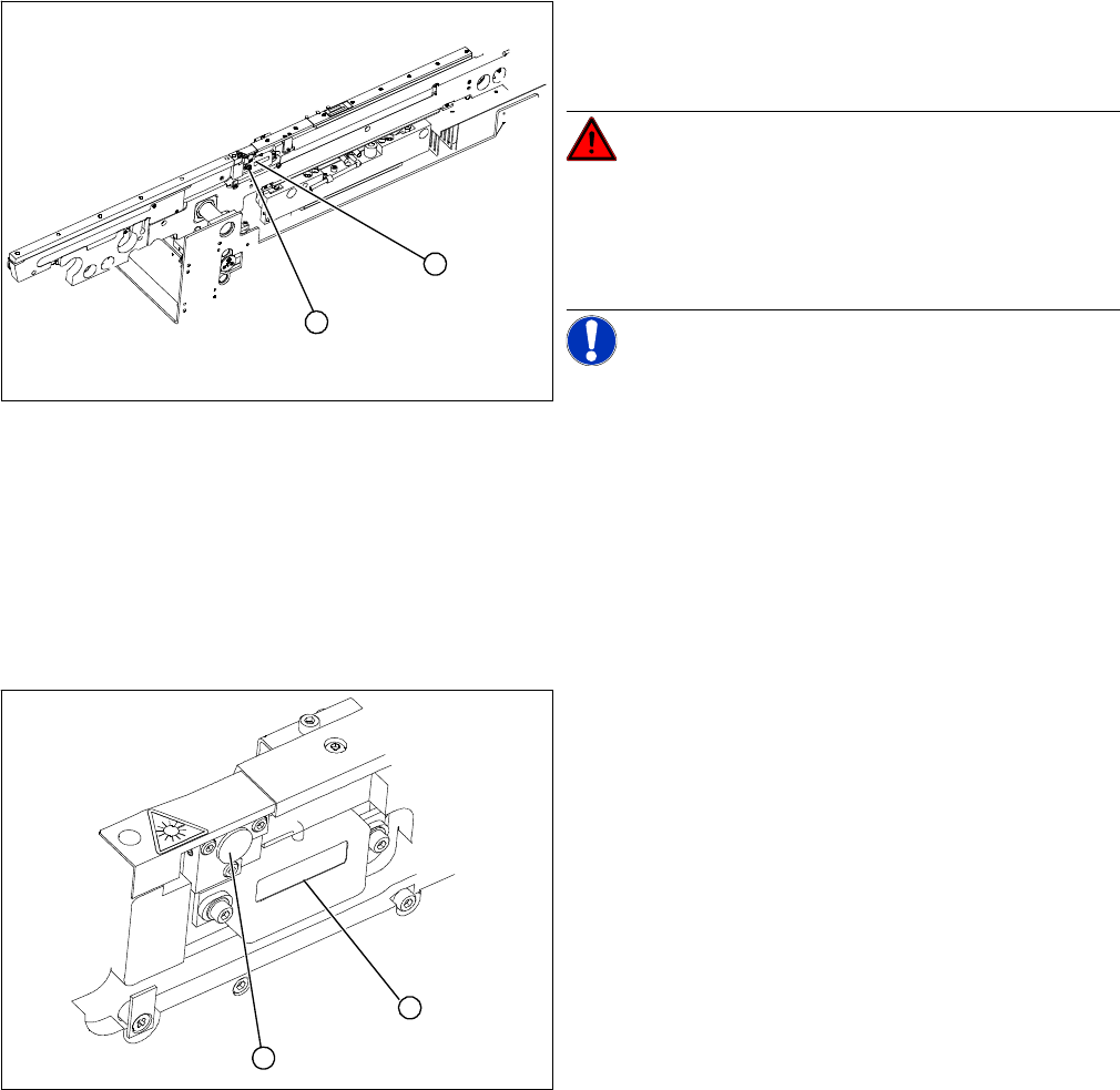
Overview
Removal/Installation of transmitter module assembly
Legend
1. Transmitter module (amplifier) with 2 screws
2. Transmitter module (round laser diode) with 3 screws
DANGER! The laser light barrier emits class 2
laser beams (from its transmitter).
You therefore do not require additional protective meas-
ures!
Keep your eyes away from the laser beam!
NOTICE! After setting the laser light barrier you
must check or re-teach the PCB reference corner!
► Move the PCB conveyor to the position which gives
you best access to the laser light barrier.
► Move the Y gantries into the area outside the PCB
conveyor.
► Switch off the machine and secure it to prevent unau-
thorized reactivation.
1
2
► Loosen the 2 fastening screws on the large transmit-
ter module (1) and the 3 fastening screws on the
small transmitter module (2). Make sure you do not
lose the O-rings.
► Unthread the connection cable as far as the relevant
conversion board of the conveyor side.
► Unplug the conversion board of the conveyor side.
► Reconnect the conversion board of the conveyor side
to the power supply and rerun the connection cable
accordingly.
► Fix the new transmitter module in the original posi-
tion.
► Make sure that the 3 O-rings are placed on the 3 fas-
tening screws.
► Switch the machine on.
► Move the conveyor system to maximum width.
► Turn the 3 fastening screws to align the transmitter di-
ode centrally to the receiver. The entire height of the
laser beam must hit the receiver. Please also refer to
the adjustment instructions.
1
2
Service Work
4.4.18 Overview of the Electrical Components PCB conveyor system
Service Manual SIPLACE D4/D4i 139
Removal /installation of receiver module
4.4.18
4.4.18 Overview of the Electrical Components
Overview of the Electrical Components
4.4.18.1
4.4.18.1 Conveyor Side Conversion Board [00359424]
Conveyor Side Conversion Board [00359424]
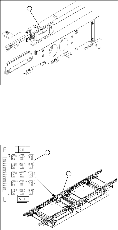
Overview
► Loosen the 2 screws fastening the receiver module
(1).
► Unthread the connection cable as far as the relevant
conversion board of the conveyor side.
► Unplug the conversion board of the conveyor side.
► Reconnect the conversion board of the conveyor side
to the power supply and rerun the connection cable
accordingly.
► Fit the new receiver module in the original position.
► Switch the machine on.
► Move the conveyor system to maximum width.
► Turn the 2 fastening screws to align the receiver cen-
trally to the transmitter diode. The entire height of the
transmitter diode laser beam must hit the receiver.
Please also refer to the adjustment instructions.
1
Legend
1. Conveyor side conversion board
2. Cover
The conversion boards for the conveyor sides (1) are sit-
uated on the respective conveyor sides, under a cover
(2).
For terminal assignment details, please refer to the cur-
rent version of the circuit diagram folder.
1
2