SIPLACE D4-D4i 工程师手册_EN.pdf - 第160页
Service Work C&P12 Placement Head 4.5.9 Replacing the Valve Positioning Drive for the Reject Circuit [00367768-xx] 160 Service Manual SIPLACE D4/D4i Legend 1. Steppi ng motor 2. Cam di sk 3. Deep-groove ball bearings…
Service Work
4.5.9 Replacing the Valve Positioning Drive for the Reject Circuit [00367768-xx] C&P12 Placement Head
Service Manual SIPLACE D4/D4i 159
See also
6.3.1 Calibrating the C&P Head and Cameras [ ➙ 206]
4.5.9.1
4.5.9.1 New Valve Positioning Drives (From Version 03)
New Valve Positioning Drives (From Version 03)
4.5.9.2
4.5.9.2 Mechanical Adjustment (Up To Version 02)
Mechanical Adjustment (Up To Version 02)
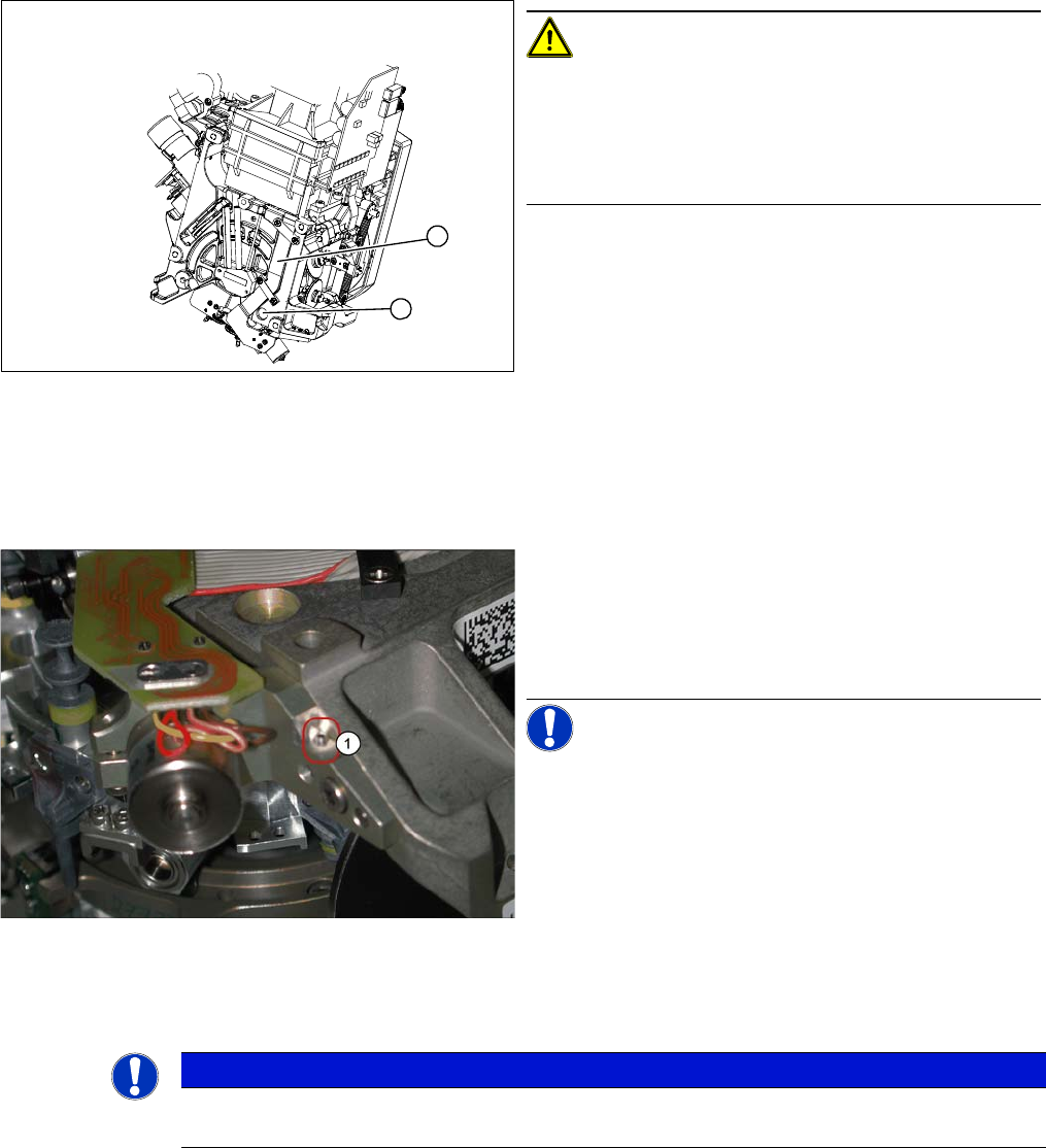
CAUTION! Check how the cables are run!
Check that the ribbon cables are laid correctly (1).
The flat ribbon cable for the two valve positioning units
must be run outside the holes (2). otherwise it will be
damaged when the C&P head is fitted onto the head
plate.
1
2
New valve positioning drive holder for the reject position
(DLM2/3) with position locking function
These valve positioning drives replace the previous ver-
sions on the DLM2/3 placement head.
For precise alignment and adjustment of the drives, use
the new tool which replaces the distance gauge 0.2 mm
[00325445-01].
NOTICE! This holder also fits the valve position-
ing drive on the placement and reject position of the
DLM1 placement head. A second 1.4 mm thread (1) is
provided on the opposite side for this purpose.
NOTICE
Instead of using the adjustment valve plungers, the DLM1 and DLM2 heads can also be set
with the distance gauge.
Service Work
C&P12 Placement Head 4.5.9 Replacing the Valve Positioning Drive for the Reject Circuit [00367768-xx]
160 Service Manual SIPLACE D4/D4i
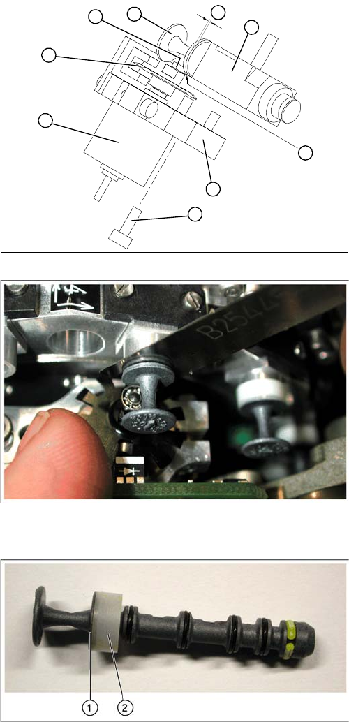
Legend
1. Stepping motor
2. Cam disk
3. Deep-groove ball bearings
4. Valve plunger
5. Valve casing
6. M3x10 hexagon socket-head screw
7. Valve positioning drive (flange)
► Use the feeler gauge to set the distance between the
valve plunger and valve casing to 0.2 mm (A).
► Turn the cam disk (2) until the deep-groove ball bear-
ings (3) point towards the valve casing.
► Move the valve positioning drive (7) so that the deep-
groove ball bearings (3) come into contact with the
valve plunger (4) at position (B).
► Use the hexagon socket-head screw to fix the adjust-
ment unit in this position (6).
► Fit the C&P head.
► Use the SITEST program to test that the valve posi-
tioning drive is functioning correctly.
► Use the SITEST program to calibrate the C&P head.
Valve plunger version 03
(C&P12: [00351498
-
03], C&P6: [00351500
-
03])
► If the new valve plungers are used (s. diag. on left)
proceed as follows:
⇨ Take out one valve plunger and remove the sleeve
(2).
⇨ Insert the plunger without bushing and carry out
the following steps on this segment:
► Insert the distance gauge (0.2 mm) between valve
plunger and valve casing.
► Rotate the valve positioning drive 90 degrees from its
initial position. The eccentric of the valve adjustment
drive will just touch the inner side (1) of the valve
plunger.
► Fix the motor of the valve drive in this position.
► Remember to replace the tube on the valve plunger.
B
A
1
7
6
5
4
3
2
Service Work
4.5.9 Replacing the Valve Positioning Drive for the Reject Circuit [00367768-xx] C&P12 Placement Head
Service Manual SIPLACE D4/D4i 161
4.5.9.3
4.5.9.3 Mechanical Adjustment (From Version 03)
Mechanical Adjustment (From Version 03)
Setting the valve positioning drive for the reject position
NOTICE
The valve positioning drives of the DLM1 and DLM3 head reject position can be set with the
adjustment valve plungers.
CAUTION
Even if your placement machine does not use the valve positioning drive for rejecting compo-
nents (rejection vertically down), the position of this drive must still be correct. If this is not the
case, an incorrectly set valve positioning drive could have a negative influence on the plunger
positions during the reference run and during star rotation.
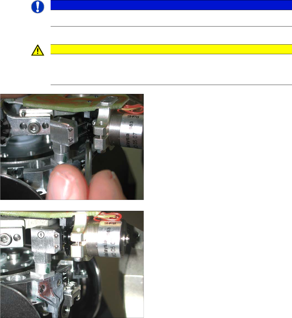
► Fit the dismantled placement head onto the head
mount and place this down on the front or place the
placement head down on a soft, ESD conductible
surface on its front.
► The lockscrew (at the bottom side of the placement
head) and the fastening screw of the valve position-
ing drive need to be loosened or are only screwed in
slightly during assembly of the drive.
► Fit the adjustment valve plunger (1) in place of the
valve plunger, for the reject position (R) - as shown in
the diagram.
► Turn the adjustment valve plunger so that the tips of
the two centering pins are near to the cam disk be-
hind the ball bearing.