SIPLACE D4-D4i 工程师手册_EN.pdf - 第206页
Settings C&P12 6.3.1 Ca librating the C&P Head and Cameras 206 Service Manual SIPLACE D4/D4i After this adjustment of the inc remental encoder you have to ch eck the zero pulse and track signals. Correct ins tall…

Settings
6.2.4 Checking the DIP Switches Gantry
Service Manual SIPLACE D4/D4i 205
6.2.4
6.2.4 Checking the DIP Switches
Checking the DIP Switches
6.2.4.1
6.2.4.1 DIP Switch on Gantry Head Distributor
DIP Switch on Gantry Head Distributor
* Not all gantries may be available, depending on the machine type.
6.2.4.2
6.2.4.2 DIP Switch on Vision Board
DIP Switch on Vision Board
* Not all gantries may be available, depending on the machine type.
6.2.5
6.2.5 Mechanical Adjustment of the Incremental Encoder
Mechanical Adjustment of the Incremental Encoder
The incremental encoders (read units) on the X and Y axis are adjusted exactly to the position of the
incremental scale. The two limit marks on the incremental encoder show where the top/bottom positions
of the scale should be. The encoder is also mechanically set to a distance of 0.4 mm +/- 0.1 mm to the
incremental scale.
S Setting for gantry* Comments
1 2 3 4
1OF
F
ON OF
F
ON P0 – gantry ID0 address switch 1 --> gan-
try
2OF
F
OF
F
ON ON P1 – gantry ID1 address switch 2 --> gan-
try
3OF
F
OF
F
OF
F
OF
F
S1 – switch for DLM head (delay switching
on LB down – Z-axis)
4OF
F
OF
F
OF
F
OF
F
BL – Enable boot loader for serial port
5OF
F
OF
F
OF
F
OF
F
Reset - CAN processor 16 Bit (TQM mod-
ule)
6OF
F
OF
F
OF
F
OF
F
C0 – no current function
7OF
F
OF
F
OF
F
OF
F
C1 – no current function
8OF
F
OF
F
OF
F
OF
F
S2 – switch for DLM head (no current
function)
S Setting for gantry* Comments
1 2 3 4
1 OFF OFF OFF OFF Boot mode - CAN processor 16
Bit via connector X11
2 OFF OFF OFF OFF Reset - CAN processor 16 Bit to
subboard
3OFF ON OFF ONP0 - Address switch 1 --> Gantry
4OFF OFF ON ONP1 - Gantry address switch 2
5 OFF OFF OFF OFF WPE - Write protect enable, cur-
rently OFF
6 OFF OFF OFF OFF CAN R - Switch terminator CAN
bus
7ONON ONONTest 1 - CAN 1 MBit/s --> ON
8ONON ONONTest 0 - CAN IDs --> ON
NOTICE
To set this distance, use one or more small plastic disks with a total thickness of 0.4 mm.
Settings
C&P12 6.3.1 Calibrating the C&P Head and Cameras
206 Service Manual SIPLACE D4/D4i
After this adjustment of the incremental encoder you have to check the zero pulse and track signals.
Correct installation should ensure correct count and zero pulse signals. For troubleshooting purposes
(error analysis and fixing), you will need to measures these signals with the oscilloscope. (See service
manual.)
6.3
6.3 C&P12
C&P12
6.3.1
6.3.1 Calibrating the C&P Head and Cameras
Calibrating the C&P Head and Cameras
Automatic calibration of all heads and cameras
6.3.2
6.3.2 Boards at C&P12
Boards at C&P12
All the settings described in this chapter are head-specific and apply here for the C&P12.
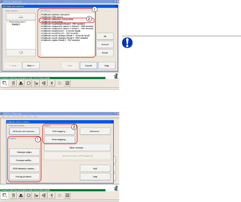
The menu may vary, according to the machine type and
configuration.
► In the SITEST menu, select Calibrate Entire Machine
--> All Heads and Cameras to open the adjacent
menu.
► In Job Selection (1) , select the components to be cal-
ibrated.
NOTICE! These two entries (2) are optional.
► To continue calibration with manual handling, select
the four consecutive menus in Section Positions (1)
and the two menu items in the Section Mapping (2).

Settings
6.3.2 Boards at C&P12 C&P12
Service Manual SIPLACE D4/D4i 207
6.3.2.1
6.3.2.1 8-fold DIP Switch of the gantry head distributor (incl. switch S1) – C&P6/12
8-fold DIP Switch of the gantry head distributor (incl. switch S1) – C&P6/12
Switch P0 and P1:
Gantry selection via switch P0 and P1
Switch S1:
▪ ON – Test mode (without delay)
▪ OFF – Default state (with delay of 3.6 ms+/- 300 us) means: Z axis moves downwards, the top LB is
released and the LB down is enabled after a delay of 3.6 ms.
See also
6.2.3.1.1 Description of LEDs on the Gantry Head Distributor [ ➙ 203]
6.2.3.1 Gantry Head Distributor [ ➙ 201]
6.3.2.2 LEDs on gantry head distributor [ ➙ 208]
DIP switch Switch position Designation
1 OFF P0 (see below)
2 OFF P1 (see below)
3 OFF "S1" for test mode (see below)
4 OFF BL – Enable boot loader for serial port
5 OFF Res (Reset) – CAN processor 16 bit (TQ module)
6 OFF C0 – no current function
7 OFF C1 – no current function
8 OFF S2 – switch for DLM head (no current function)
S Gantry 1 Gantry 2 Gantry 3 Gantry 4 Designation
1 OFF ON OFF ON P0
2 OFF OFF ON ON G1