SIPLACE D4-D4i 工程师手册_EN.pdf - 第26页
Overview Electrical System 3.2.2 Power Supply Unit 26 Service Manual SIPLACE D4/D4i EMERGENCY STOP loops
Overview
3.2.2 Power Supply Unit Electrical System
Service Manual SIPLACE D4/D4i 25
The two signaling contacts for the EMERGENCY STOP buttons are connected in parallel and form the
"EMERGENCY STOP push-button signal circuit". When an EMERGENCY-STOP button is pressed, a
24 V signal is sent to the CAN bus and signals that one of the EMERGENCY-STOP buttons has been
pressed.
The four signalling contacts for the push-button flaps are connected in parallel. They form the "Flap sig-
nal" circuit. If one or more flaps are raised, a 24 V signal will be applied to the CAN bus, signaling that
one of the cover flaps is not closed.
The four signalling contacts for the CO trolleys are connected in series and form the "changeover table"
signal loop. If a CO trolley is missing, a 0 V signal is sent to the CAN bus. If all trolleys are connected,
the signal is approximately 16 V.
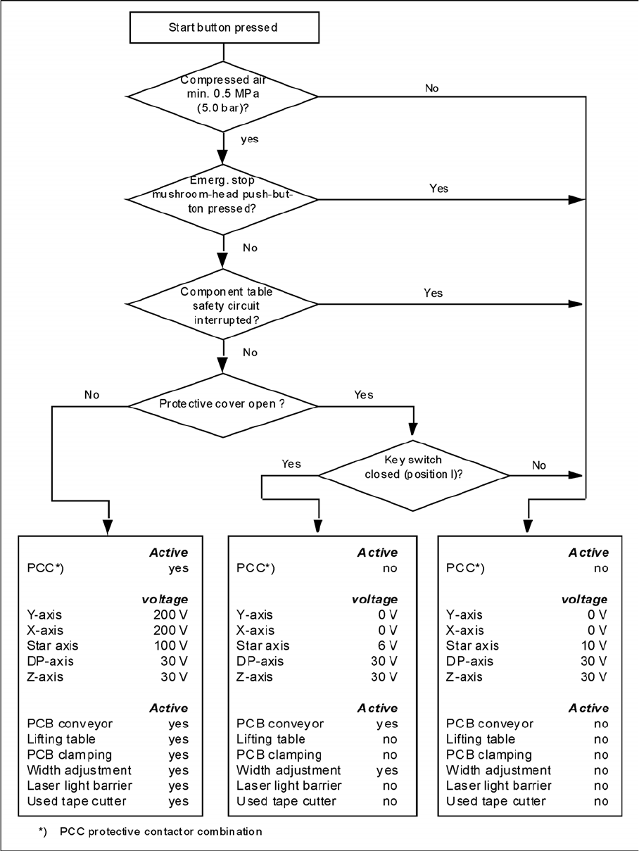
EMERGENCY STOP loop functions
The following conditions must be fulfilled before the placement system can be started or operated:
▪ all four component trolleys must be docked in and connected.
▪ All protective covers must be closed.
▪ Both cover flaps over the PCB conveyor must be closed.
▪ Both emergency stop pushbuttons must be released.
▪ all four flaps over the push-buttons for raising the CO tables must be closed.
▪ The minimum operating pressure must have been reached.
▪ The "software enable" signal must be active. This ensures that the EMERGENCY STOP loop is
closed.
▪ The power supply sends 24 V to the start buttons and the protective contactor combination.
▪ If one of the start buttons is now pressed, the protective contactor combination PCC will switch and
activate the following components:
– 200 V link voltage for the servo amplifiers of the gantry axes
– 150 V link voltage for the star axes
– The axis unit will receive a "Servo Enable" signal for the servo amplifier.
– 34 V operating voltage is switched to the component trolleys.
– 24 V operating voltage is switched to the used tape cutters.
– The PCB conveyor control receives the enable signal for the PCB clamping, the PCB stopper
and the lifting table control.
The machine is then ready for use.
Overview
Electrical System 3.2.2 Power Supply Unit
26 Service Manual SIPLACE D4/D4i
EMERGENCY STOP loops
Overview
3.2.3 Distributors in Sectors 1-4 Electrical System
Service Manual SIPLACE D4/D4i 27
3.2.3
3.2.3 Distributors in Sectors 1-4
Distributors in Sectors 1-4
3.2.3.1
3.2.3.1 Distributors in Sector 1
Distributors in Sector 1
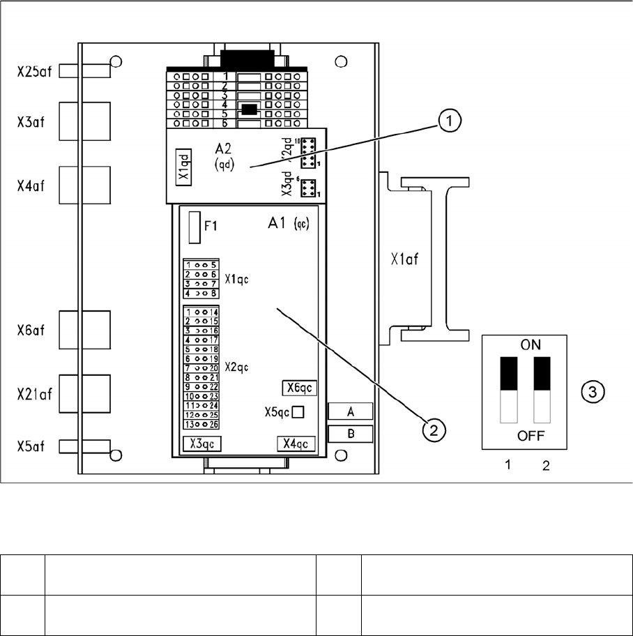
Overview - distributors in sector 1
Legend
1 Vision DC/DC converter [03002280-xx] 3 DIP switch for CAN Bus terminator for CO
table in Sector 1
2 CAN Bus Terminator Board for Changeo-
ver Table [03046863-xx]