SIPLACE D4-D4i 工程师手册_EN.pdf - 第187页
Service Work 4.5.25 Replacing the Vacuum Hoses on the C&P Head C&P12 Placemen t Head Service Manual SIPLACE D4/D4i 187 Removal/installation ► Mark the connection points a nd the route of the individual hose s, so…
Service Work
C&P12 Placement Head 4.5.25 Replacing the Vacuum Hoses on the C&P Head
186 Service Manual SIPLACE D4/D4i
Removal
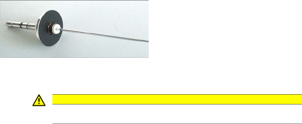
► Loosen the old membrane with an Allen key (1.5 mm) and remove the membrane.
Installation
► Fit the new membrane onto the sleeve and tighten the membrane with an Allen key.
4.5.25
4.5.25 Replacing the Vacuum Hoses on the C&P Head
Replacing the Vacuum Hoses on the C&P Head
The length of the vacuum hoses and the way in which they are fitted has been improved to ensure that,
when the hoses are replaced - especially in SX, DX, X, D3 and HF machines - these hoses can be run
in a manner which will not interrupt the vacuum supply.
Tools and equipment
▪ Standard tool
▪ Spare part: vacuum hoses and guidance [03064147-xx]
Contents:
– Hose for placement circuit query (new length: 180 mm, old length: 190 mm) [03002187-02]
– Hose for holding circuit query (new length: 225 mm, old length: 200 mm) [03002188-02]
– Hose for placement circuit / 3x6x145 (new length: 145 mm, old length: 125 mm) [03010444-02]
– Hose for hold circuit / 4x7x140 [03010445S01]
– Hose guide [03048807-01]
– Cylinder screw M3x6 DIN912-A2 [03045028-01]
White membrane for the sleeve with ball fixing C&P6/12,
made of an alternative material
(new version [03037984-xx])
CAUTION
Do not use a ball Allen key!
► Make sure that you do not use a ball Allen key.
Service Work
4.5.25 Replacing the Vacuum Hoses on the C&P Head C&P12 Placement Head
Service Manual SIPLACE D4/D4i 187
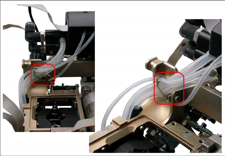
Removal/installation
► Mark the connection points and the route of the individual hoses, so that these can be rerun correctly
later on.
► Disconnect the hoses from the vacuum generator and the vacuum measuring board.
► Fit the additional hose guide (M3 screw) on the top measuring hose duct.
► Fit the new hose as shown in the diagrams.

Service Work
Pneumatic Unit 4.6.1 Safety Instructions for Replacing Parts
188 Service Manual SIPLACE D4/D4i
4.6
4.6 Pneumatic Unit
Pneumatic Unit
4.6.1
4.6.1 Safety Instructions for Replacing Parts
Safety Instructions for Replacing Parts
4.6.2
4.6.2 Preparing for Part Replacement
Preparing for Part Replacement
► End all placement operations on the placement system.
► Shut down the Windows NT operating system correctly, otherwise problems may occur when restart-
ing or data may be lost.
► Switch the placement system off at the main switch.
► Disconnect the machine from the power supply.
► Secure the machine to prevent it being switched on again and put up warnings signs to indicate that
service work is in progress.
WARNING
NEVER disconnect compressed air lines while they are still pressurized. Risk of injury!
DANGER
The machine is supplied with 3 x 400 V~ (or 3 x 204 V~ / 3 x 230 V~ / 3 x 380 V~ / 3 x 415 V~)
± 5 %, 50/60 Hz mains voltage.
Consequently, parts of the system carry potentially lethal voltages, even when it is switched off
at the main switch.
Incorrect handling of the machine can therefore result in death, severe injury or considerable
damage to equipment.
Measurements and repairs must always be carried out by appropriately qualified personnel.
Always follow the safety instructions in this manual.
Always follow the applicable accident prevention and VDE regulations (particularly DIN EN 60
204 part 1) or the regulations specific to your country.
Before starting any repairs, switch off at the main switch and disconnect the machine from the
mains power supply.
Secure the system to prevent it being switched on again. If these instructions are not followed,
you may be able to touch live parts, which could result in death or severe injury.