4OM-1733-005w_F8.pdf - 第139页
4OM-1733 1-5-6 1208-001 5.5 Cleaning of high-speed nozzle hole part with pin gauge 5.5 Cleaning of high-speed nozzle hole part with pin gauge After the ultrasonic cleaning, conrm the clog of the nozzle hole with the mag…
4OM-1733
1-5-5
1208-001
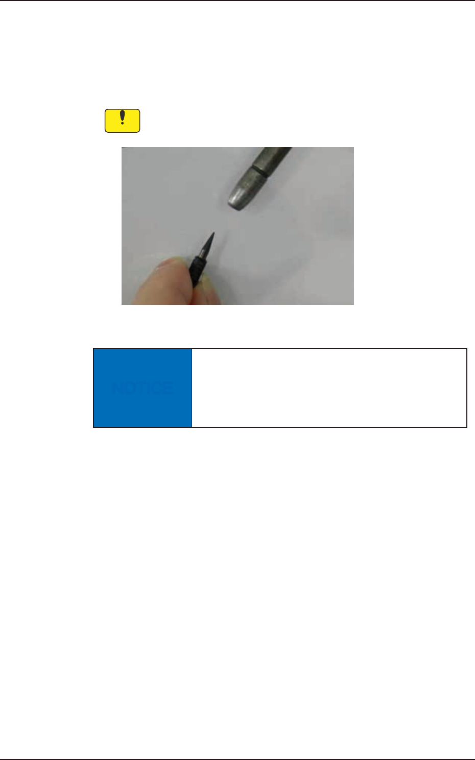
5.4 Method of Blow air
5.4 Method of Blow air
•
Remove dust and dirt etc.
Remove slight dust and dirt by blow air or wiping off.
Clean the tapered area of the vacuum nozzle with a lens cleaning cloth.
Notice
Use clean, dry, and non-lubricated air for blow air.
Fig. 4A5-4
NOTICE
Blow air to the head when blow air to the nozzle.
There is a possibility that the clamp jaw breaks when
the air blow is done from the direction of the clamp
jaw to the nozzle.
4OM-1733
1-5-6
1208-001
5.5 Cleaning of high-speed nozzle hole part with pin gauge
5.5 Cleaning of high-speed nozzle hole part with pin gauge
After the ultrasonic cleaning, conrm the clog of the nozzle hole with the
magnifying glass.
When the clog is conrmed, clean it with the pin gauge.
•
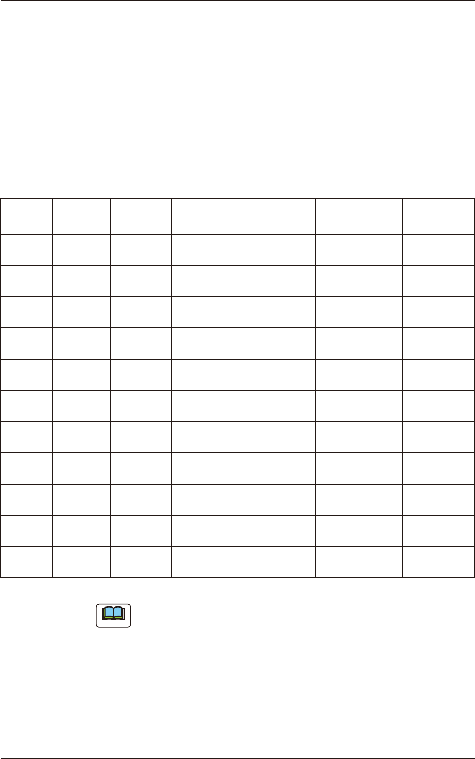
Select pin gauge
The pin gauge used is different depending on the kind of a high-speed nozzle.
Please select it referring to the combination shown next.
Unit : mm Table 4A5-1
Nozzle ID
Diameter
(center hole
diameter)
Diameter
(minimum hole
diameter)
Pin gauge
size
Part No.
Direction of pin
gauge insertion
Nozzle Tip
Cleaning Jig
HG24C
f
0.1
f
0.08
f
0.08
KYB-M384L-00
0942J1A9
Nail side, Head
side
KYB-M384P-00
0942J1AH
HG33C
f
0.2
f
0.08
f
0.12
KYF-M861K-00
0942J1AC
Nail side, Head
side
KYB-M384R-00
000942J1A5
HG52C
f
0.4
f
0.25
f
0.2
KYF-M861L-00
0942J1AD
Nail side, Head
side
HG82C
f
0.7
f
0.35
f
0.3
KYF-M862U-00
0942J1AE
Head side (a)
HV82C
f
0.7
f
0.35
f
0.3
KYF-M862U-00
0942J1AE
Nail side, Head
side
HG13C
f
0.9
f
0.9
f
0.6
KYB-M384M-00
0942J1AF
Head side (a)
HV13C
f
0.9
f
0.9
f
0.6
KYB-M384M-00
0942J1AF
Nail side, Head
side
HG14C
f
1.1
f
1.1
f
0.8
KYB-M384N-00
0942J1AG
Head side (a)
HV14C
f
1.1
f
1.1
f
0.8
KYB-M384N-00
0942J1AG
Nail side, Head
side
HG15C
f
2.0
f
1.1
f
0.8
KYB-M384N-00
0942J1AG
Head side (a)
HV15C
f
2.0
f
1.1
f
0.8
KYB-M384N-00
0942J1AG
Nail side, Head
side
Note
(a) Pin gauge can not be inserted from nail side.
4OM-1733
1-5-7
1208-001
5.5 Cleaning of high-speed nozzle hole part with pin gauge
•
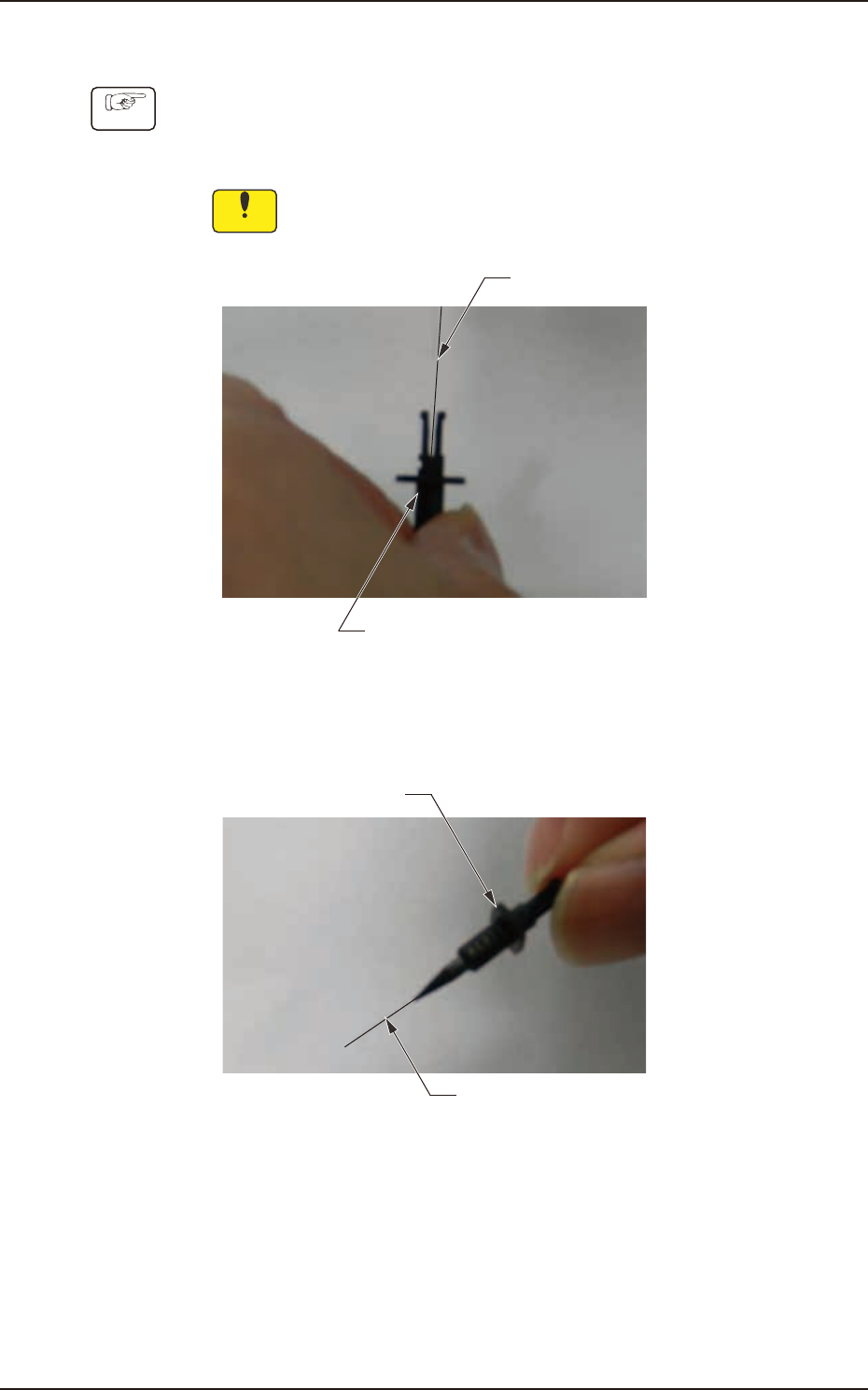
Method of cleaning high-speed nozzle hole
Procedure
(1) Firmly have the high-speed nozzle as shown in the following photograph
and insert it while matching a pin gauge center axis to a center axis of
a high-speed nozzle.
Notice
When a center axis shifts, the head might be damaged.
Pin gauge
High-speed nozzle
Fig. 4A5-5
(2) Put out the pin gauge from the head of the high-speed nozzle.
High-speed nozzle
Pin gauge
Fig. 4A5-6