4OM-1733-005w_F8.pdf - 第142页
4OM-1733 1-5-9 121 1-002 5.6 Nozzle Filter Insertion Procedure 5.6 Nozzle Filter Insertion Procedure • For High-Speed Nozzle Procedure (1) Set the nozzle lter in the hole section. Filter Fig. 4A5-9 (2) Set the nozzle on…
4OM-1733
1-5-8
1208-001
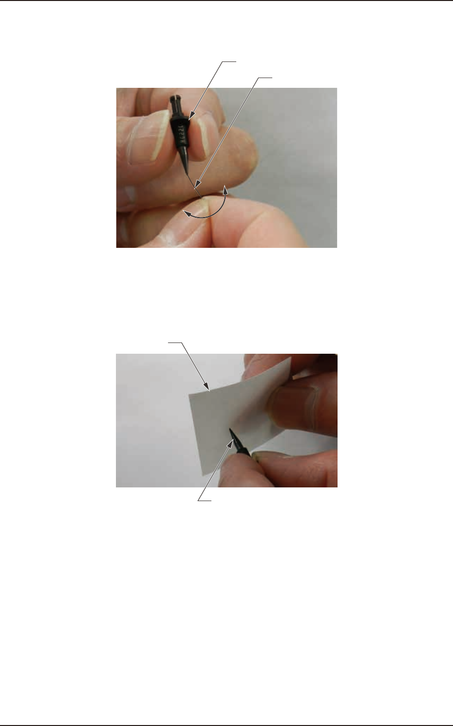
5.5 Cleaning of high-speed nozzle hole part with pin gauge
(3) Move the pin gauge to the direction of the length hand of pick-up hole and
remove the internal clog.
Pin gauge
High-speed nozzle
Fig. 4A5-7
(4) Blow air and blow away removed dirt (Stick and remove the ne dirts of the
high-speed nozzle head by the masking tape).
High-speed nozzle
Masking tape
Fig. 4A5-8
4OM-1733
1-5-9
1211-002
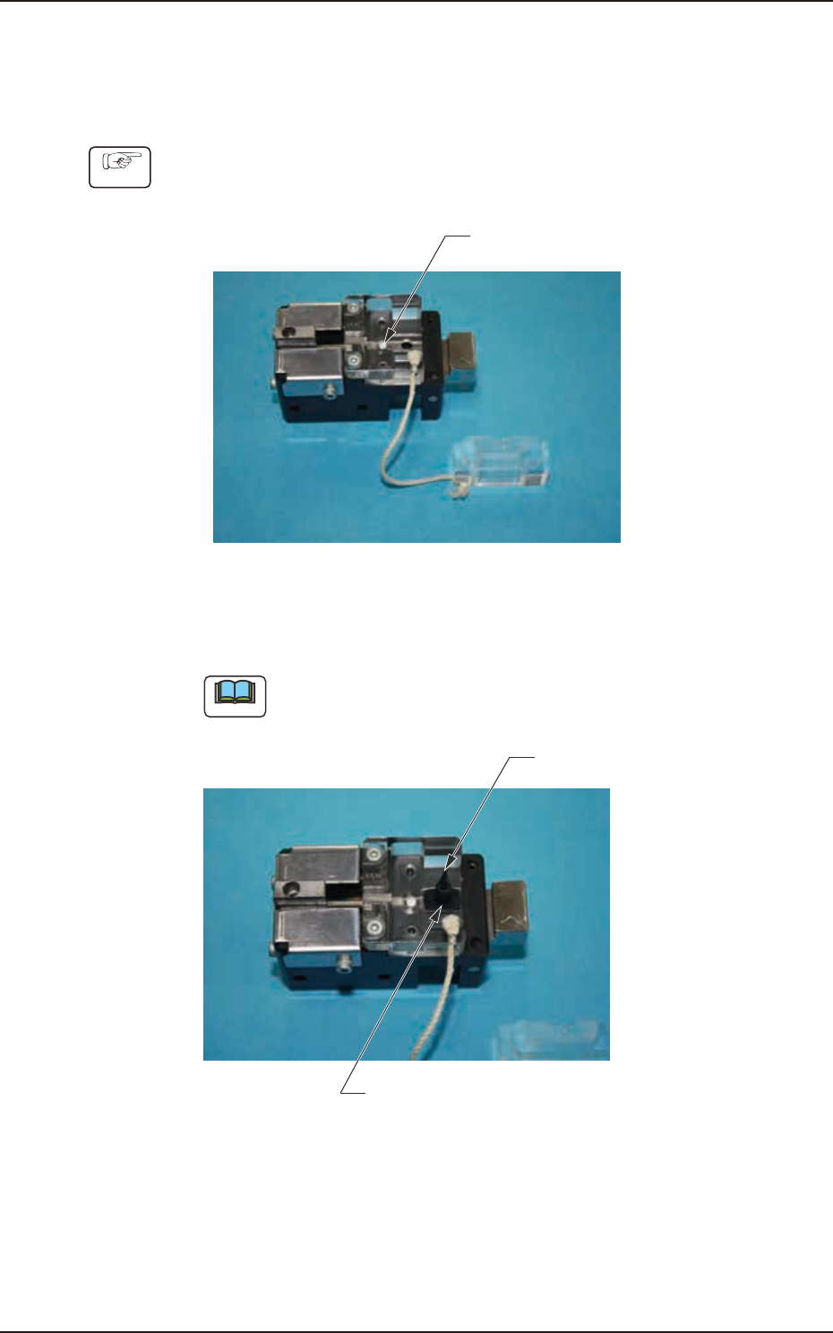
5.6 Nozzle Filter Insertion Procedure
5.6 Nozzle Filter Insertion Procedure
•
For High-Speed Nozzle
Procedure
(1) Set the nozzle lter in the hole section.
Filter
Fig. 4A5-9
(2) Set the nozzle on the hole section shown in the gure.
Note
Make sure that the nozzle orientation is correct.
Nozzle
Setting Position (Hole Section)
Fig. 4A5-10
4OM-1733
1-5-10
1211-002
5.6 Nozzle Filter Insertion Procedure
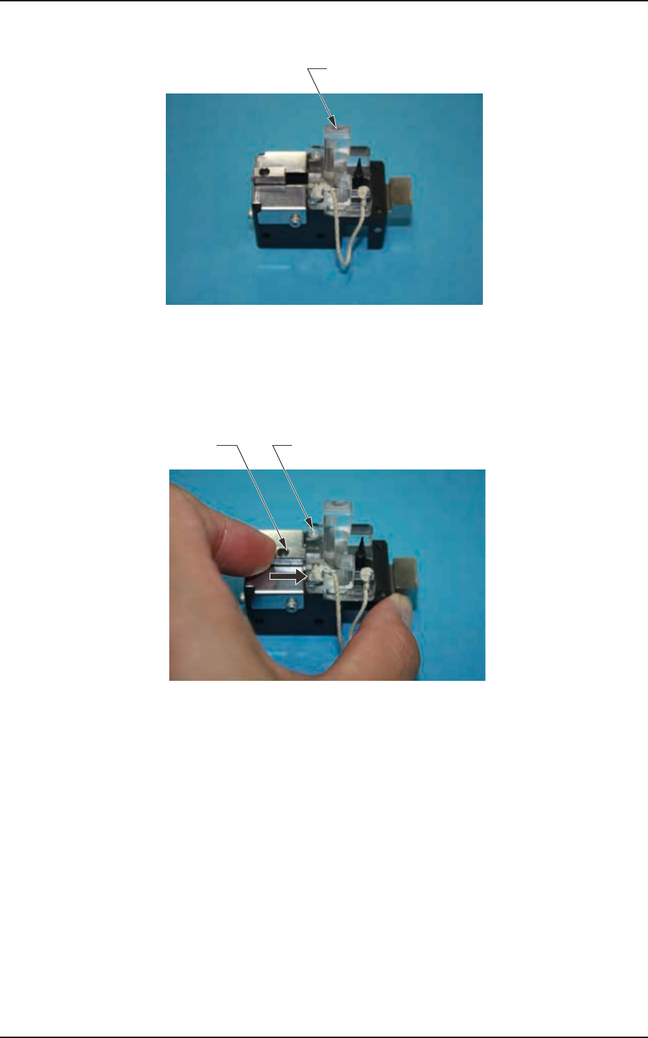
(3) Insert the lter holding block into the opening section of the lter set.
Filter Holding Block
Fig. 4A5-11
(4) Push the sliding section up to the main body acrylic block end and insert the
nozzle lter.
Main Machine Acrylic BlockSlide it.
Fig. 4A5-12