4OM-1733-005w_F8.pdf - 第143页
4OM-1733 1-5-10 121 1-002 5.6 Nozzle Filter Insertion Procedure (3) Insert the lter holding block into the opening section of the lter set. Filter Holding Block Fig. 4A5-11 (4) Push the sliding section up to the main b…
4OM-1733
1-5-9
1211-002
5.6 Nozzle Filter Insertion Procedure
5.6 Nozzle Filter Insertion Procedure
•
For High-Speed Nozzle
Procedure
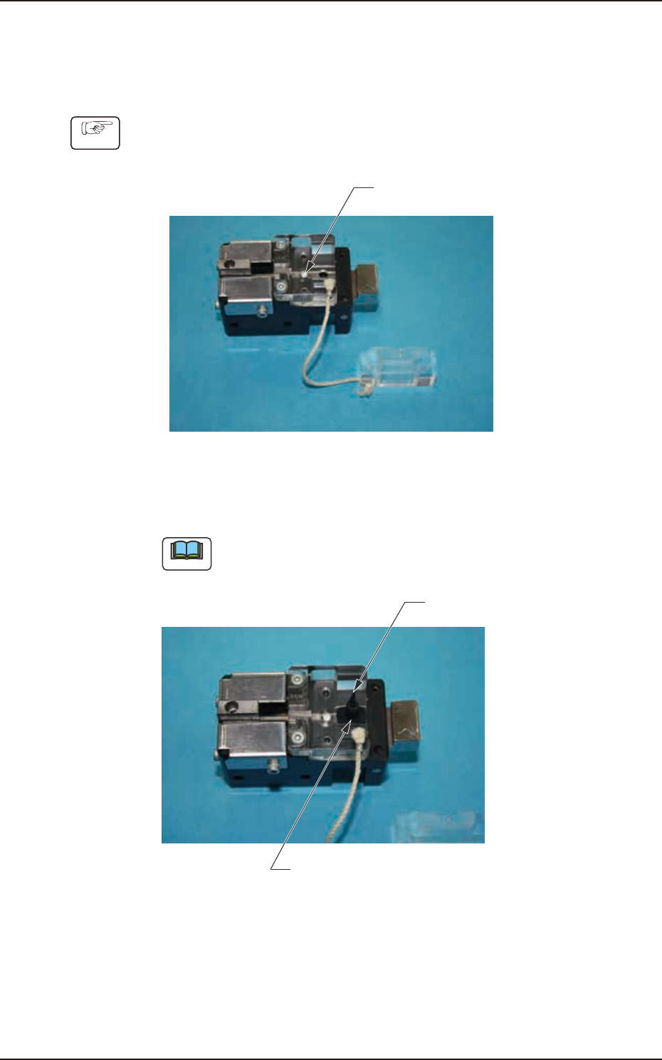
(1) Set the nozzle lter in the hole section.
Filter
Fig. 4A5-9
(2) Set the nozzle on the hole section shown in the gure.
Note
Make sure that the nozzle orientation is correct.
Nozzle
Setting Position (Hole Section)
Fig. 4A5-10
4OM-1733
1-5-10
1211-002
5.6 Nozzle Filter Insertion Procedure
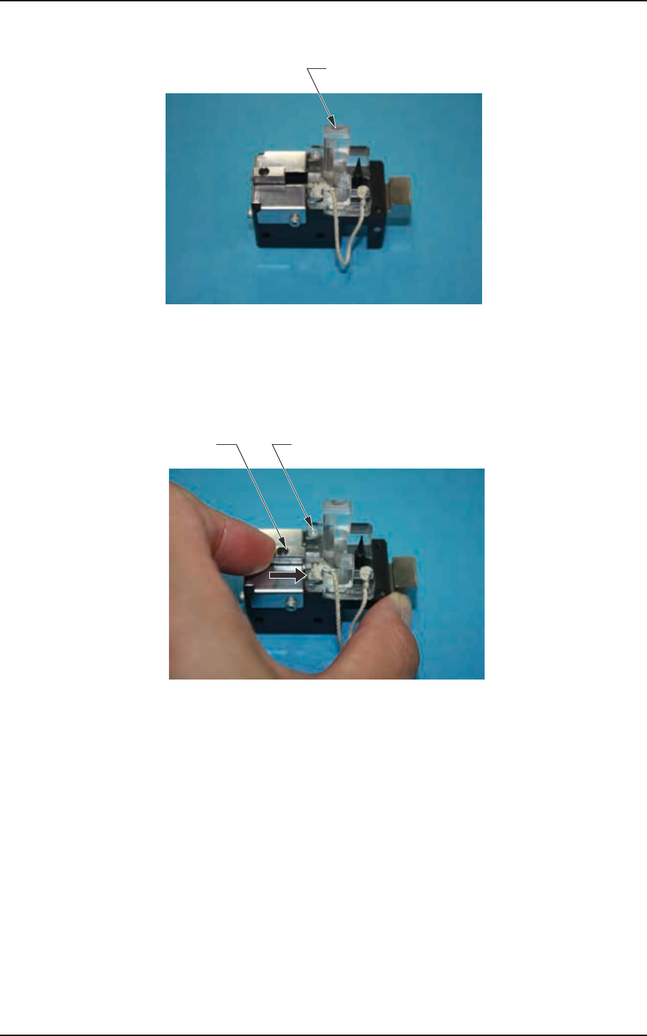
(3) Insert the lter holding block into the opening section of the lter set.
Filter Holding Block
Fig. 4A5-11
(4) Push the sliding section up to the main body acrylic block end and insert the
nozzle lter.
Main Machine Acrylic BlockSlide it.
Fig. 4A5-12
4OM-1733
1-5-11
1211-001
5.6 Nozzle Filter Insertion Procedure
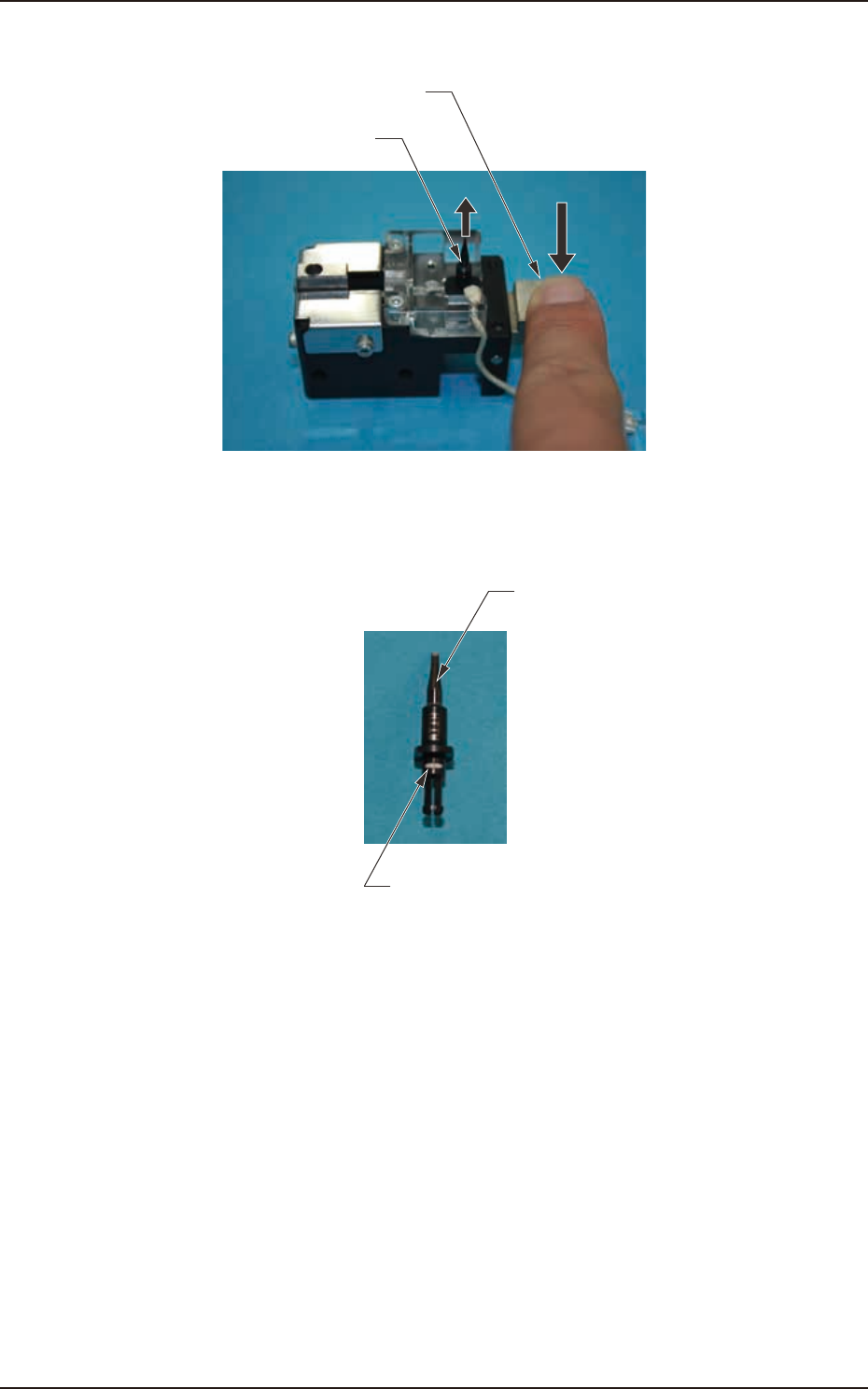
(5) Push the lever down to remove the nozzle.
Nozzle
Lever
Rising
Fig. 4A5-13
(6) Make sure that the nozzle lter has been inserted.
Nozzle
Nozzle Filter
Fig. 4A5-14