ServiceInstruction_Vision XP.pdf - 第102页
Page 98 Vision XP+ V AC 3 Setup Instructions 3.10 V olume flow control, cooling section parameters Operating Instructions V ersion 1.5 I) Start Start the filter check manually (for test purposes). J) Filter F9 OK Status …
Vision XP+ VAC Page 97
3 Setup Instructions
3.9 Filter F9 Parameter
Operating Instructions
Version 1.5
H) Real maximum value
Real value corresponding to the analog maximum value.
I) N2 consumption limit value
N2 consumption from which a warning is indicated due too high con-
sumption.
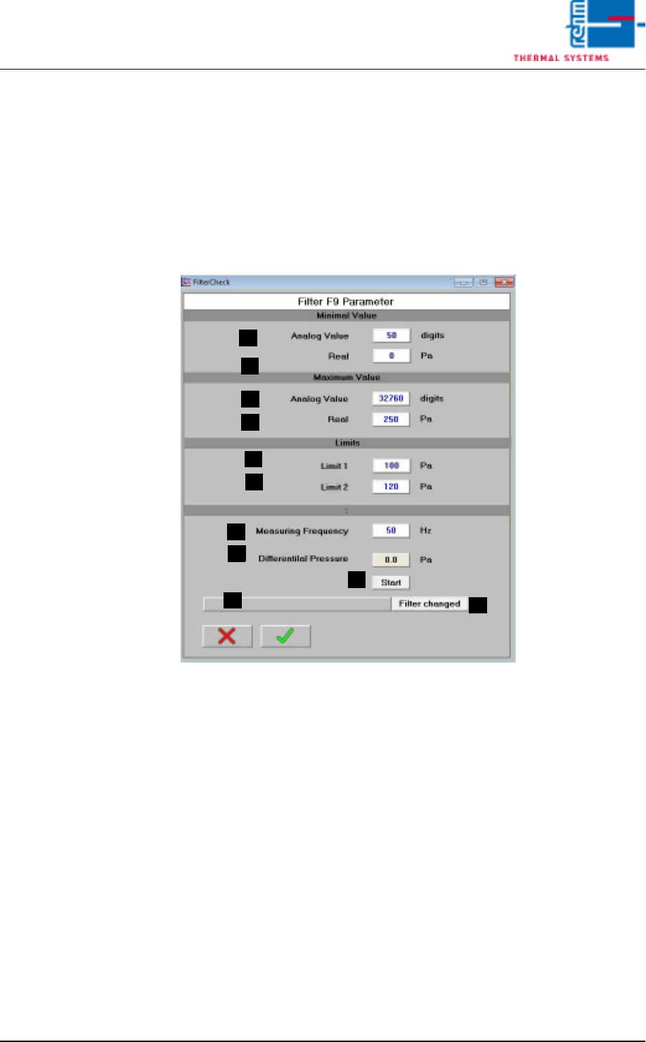
3.9 Filter F9 Parameter
A) Analog Value Minimum Value
Analog Value, which matches the Real Minimum Value.
B) Real Minimum Value
Real Value, which matches the Analog Minimum Value.
C) Analog Value Maximum Value
Analog Value, which matches the Real Maximum Value.
D) Real Maximum Value
Real Value, which matches the Analog Maximum Value.
E) Limit Value 1
Differential pressure for warning message
F) Limit Value 2
Differential pressure for message with the demand of filter change.
G) Test frequency
Frequency for the frequency converter of the cooling section during the
measurement for the filter checking.
H) Differential pressure
Current differential pressure at the filter.
A
B
C
D
E
F
G
H
I
J
K
Page 98 Vision XP+ VAC
3 Setup Instructions
3.10 Volume flow control, cooling section parameters
Operating Instructions
Version 1.5
I) Start
Start the filter check manually (for test purposes).
J) Filter F9 OK
Status display Filter F9
K) Filter replaced
Key button for reset of the filter status after the replacement.
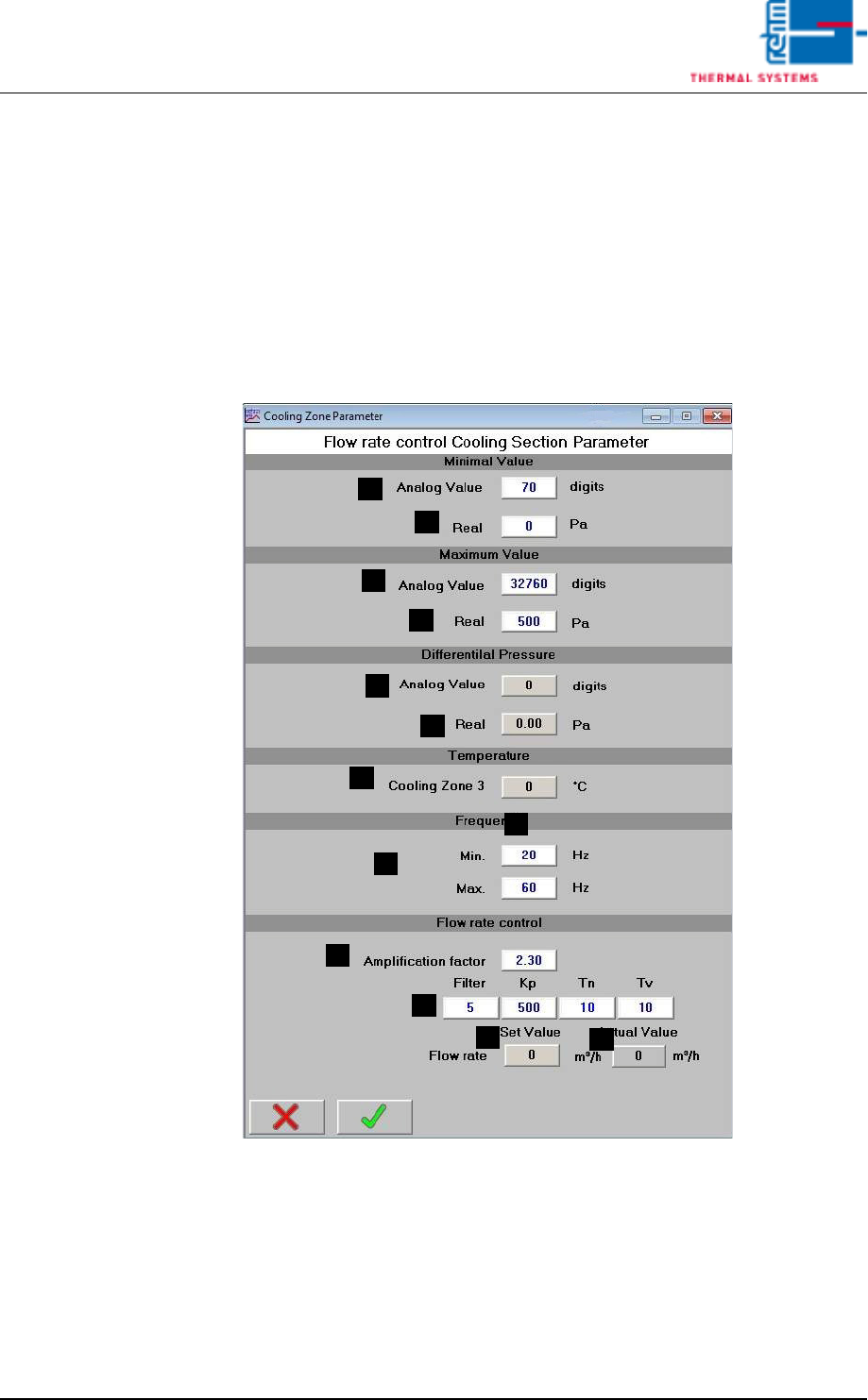
3.10 Volume flow control, cooling section parameters
Fig. 3-14 Volume flow control, cooling section parameter
These parameters are set by the Rehm Thermal Systems GmbH Service
technican during commissioning.
A) Analog Value
Raw value
B) Actual
Differential pressure
A
B
A
B
A
B
C
D
I
E
F
G
H

Vision XP+ VAC Page 99
3 Setup Instructions
3.10 Volume flow control, cooling section parameters
Operating Instructions
Version 1.5
Adjustment values for differential pressure measurement: Used to adjust
to the differential pressure sensor in use.
C) Cooling zone 3
Temperature to calculate volume flow.
D) Frequency min/max control range of frequency converter for fan speeds.
E) Amplification factor
Measuring path adjustment. Measuring procedure is described separate-
ly.
F) Filter KP, Tn, Tv
Setting parameters for controller function. These should remain at the
specified values.
G) Volume flow Set-point value
Display of set-point value as set on the fan screen.
H) Volume flow Actual value
Current value.