ServiceInstruction_Vision XP.pdf - 第81页
Vision XP+ V AC Page 77 3 Setup Instructions 3.3 Conveyor Operating Instructions V ersion 1.5 3.3.2 Conveyor Adjustment Fig. 3-7 Conve yor Adj ustment – Paramet ers A) Conveyor adjustm ent can be operated eith er automat…

Page 76 Vision XP+ VAC
3 Setup Instructions
3.3 Conveyor
Operating Instructions
Version 1.5
F) Filter
Number of measured values which are averaged together for the actual
value display. A high number results in a stable display value, although
changes to the display value appear very slowly in this case. The default
setting is 10.
G) CCS
Number of measured values which are averaged together for CCS data
logging. This value must correspond with the CCS software settings. The
default setting is 10.
H) Offset
In the closed-loop control mode, the difference between the setpoint and
the actual value is continuously ascertained. An offset is generated
cyclically from this difference for the motor controller module. The current
offset value is displayed here, and minimum and maximum values can be
entered. The default setting is ± 500.
I) Setup Mode / Closed-Loop Control Mode
Settings can be adjusted at the motor controller module in the setup
mode. Offset for the motor controller module is deactivated.
Settings may not be adjusted at the motor controller module in the
closed-loop control mode. Offset for the motor controller module is
activated.
The default setting is closed-loop control mode.
J) Setpoint / Actual Value
Conveyor speed is changed by entering a new setpoint (white field). The
actual value is displayed in the adjacent field.
K) Motor current
Set speed to1800 mm per minute. Switch the conveyor on a read the an-
alog value. Enter this value to „Max. Analog IN“. Connect the ammeter in
series to the motor and read the actual value (mA). Enter the mA value
to „Max. mA“.
To make check the
Speed
1. Turn the conveyor on and check to see whether or not the belt pulse
sensor switches accurately.
2. Open the conveyor window.
3. Set the speed setpoint to 1000 mm per minute, and set manipulated
variable limiting Ymax to 100%.
4. Open the Conveyor Drives window from the service menu.
5. Make sure that switch I is set to setup mode. If not, click switch I. The
text is changed from “Closed-Loop Control Mode” to “Setup Mode”.
6. In order to determine conveyor speed, time required for 1000 mm of
travel must be checked with the help of a stopwatch and a link pin
identified for this purpose.
7. Set switch I back to closed-loop control mode.
8. Save the system parameters to memory.
Vision XP+ VAC Page 77
3 Setup Instructions
3.3 Conveyor
Operating Instructions
Version 1.5
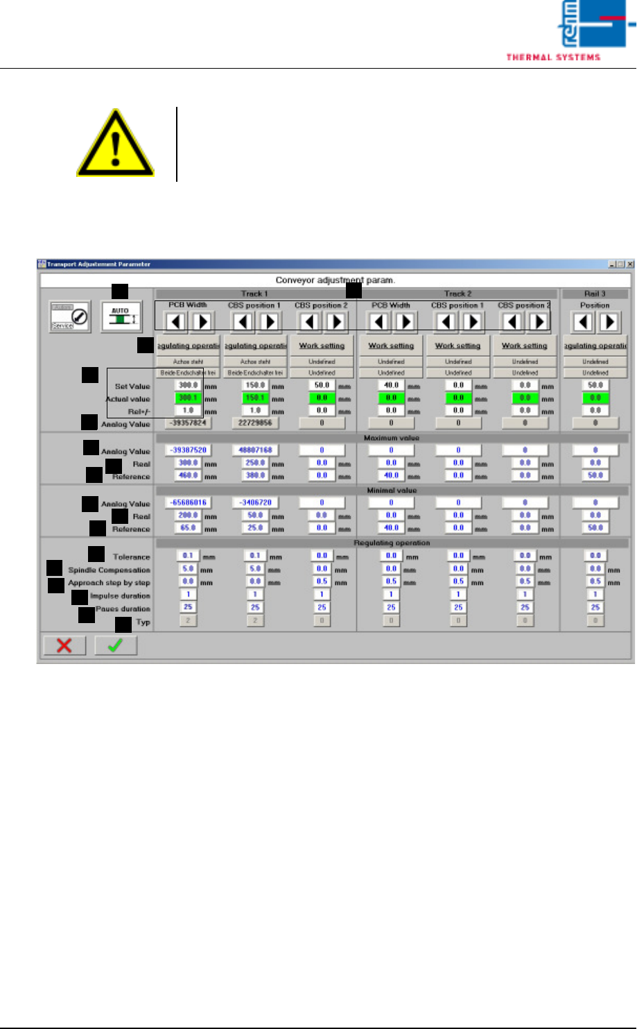
3.3.2 Conveyor Adjustment
Fig. 3-7 Conveyor Adjustment – Parameters
A) Conveyor adjustment can be operated either automatically or manually.
For further details refer to Main Window, in the chapter entitled “Software”
in the Operating Instructions.
B) Setpoints can be entered here, actual values are displayed and conveyor
tolerances can be entered. Beyond this, the status displays for the
conveyor units (axis) and error messages which have been triggered by
a PCB or the center support can be viewed. For further details refer to
Conveyor Values in the chapter entitled “Software” in the Operating
Instructions.
C) Setup Mode / Closed-Loop Control Mode
The conveyor side panels can be calibrated in the setup mode. Automatic
adjustment is deactivated for all conveyor side panels.
The conveyor side panels cannot be calibrated in the closed-loop control
mode. Automatic adjustment is activated. The default setting is closed-
loop control mode.
Note!
If a dual lane conveyor with asynchronous speed is utilized, the conveyor
speed for lane 2 must be checked separately using the same procedure.
A
C
B
B
D
E
F
G
H
I
J
K
L
M
N
O
P

Page 78 Vision XP+ VAC
3 Setup Instructions
3.3 Conveyor
Operating Instructions
Version 1.5
D) Analog Value
The analog value which is currently being acquired from the rotary
encoder is displayed here.
E) Analog Value, Maximum Values
Acquired analog value (D) which corresponds to the actual value (F).
F) Actual Maximum Values
Actual value which corresponds to the analog value (E).
G) Homing, Maximum Values
Entry of the maximum value for homing.
H) Analog Value, Minimum Values
Acquired analog value (D) which corresponds to the actual value (I).
I) Actual Minimum Values
Actual value which corresponds to the analog value (H).
J) Homing, Minimum Values
Entry of the minimum value for homing.
K) Tolerance
Control tolerance for automatic conveyor adjustment. The default
setting is 0.1.
L) Spindle Compensation
Spindle compensation for automatic conveyor adjustment. Spindle
compensation assures that the conveyor side panel is always
approached from the same side during automatic conveyor adjustment.
Mechanical tolerances and overrunning are compensated for in this way.
A value of greater than 0 always results in approach from the outside. A
value of less than 0 always results in approach from the inside. The
magnitude of the value determines to what extent the setpoint will be
overshot.
The default setting is 0.0.
M) Incremental Approach
Incremental approach allows for pulse controlled conveyor adjustment
just before the setpoint is reached. The default setting is 0.0.
N) Pulse Duration
The duration of the pulse for incremental approach is specified here. The
default setting is 1.
O) Pause Duration
The duration of the pause for incremental approach. The default setting
is 25.
P) Type
The type of conveyor side panel.
0 = no side panel
1 = side panel with manual conveyor adjustment
2 = side panel with automatic conveyor adjustment
Proceeding calibration
of PCB-width
Transport system has to be parallel for calibration!
1. Open the mask „Set-up“ in menu „Service“ and check if the transport is
released.
2. Switch the Automatic Width Adjustment to manual in the main mask.