ServiceInstruction_Vision XP.pdf - 第41页
Vision XP+ V AC Page 37 2 Maintenance 2.8 V acuum Unit Operating Instructions V ersion 1.5 2.8.7 Check the chain slack Fig. 2-5 2 Che ck the ch ain slack Slack in the transp ort chain in the vacuum chamber mu st be check…
Page 36 Vision XP+ VAC
2 Maintenance
2.8 Vacuum Unit
Operating Instructions
Version 1.5
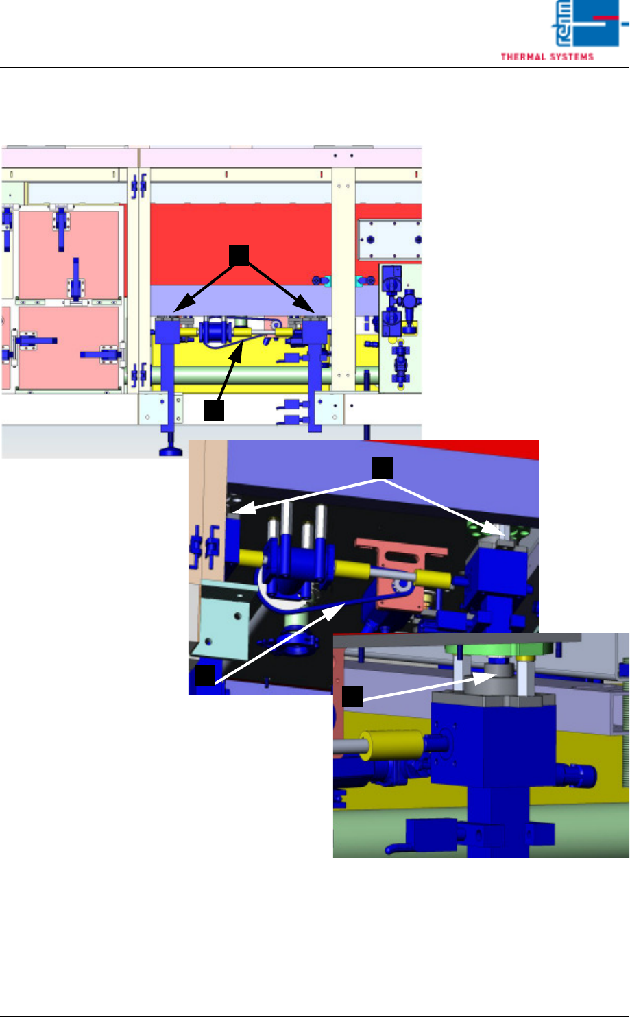
2.8.6 Back of plant below the vacuum chamber
Fig. 2-51 Back of plant below the vacuum chamber
1. Oil the spindles, then open and close vacuum chamber several times.
2. Chain tension (1 cm)
1
2
1
1
2
Vision XP+ VAC Page 37
2 Maintenance
2.8 Vacuum Unit
Operating Instructions
Version 1.5
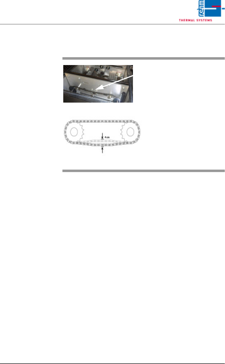
2.8.7 Check the chain slack
Fig. 2-52 Check the chain slack
Slack in the transport chain in the
vacuum chamber must be checked
from time to time.
The chain should have no more
than 4 cm slack.
The chain can be adjusted using the
chain tensioner.
Page 38 Vision XP+ VAC
2 Maintenance
2.8 Vacuum Unit
Operating Instructions
Version 1.5
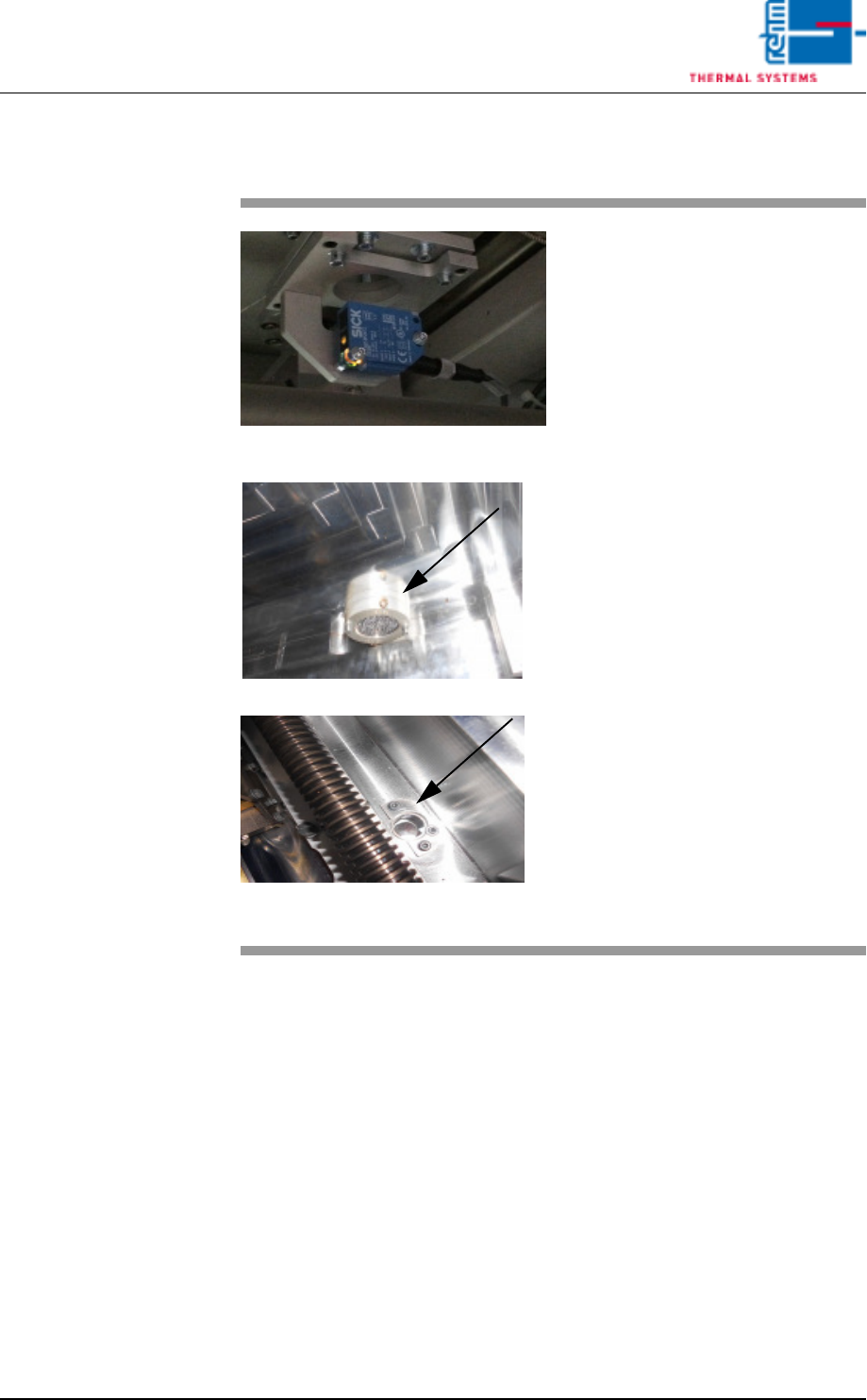
2.8.8 Sensors in the vacuum chamber
Fig. 2-53 Sensors for the vacuum chamber
Fig. 2-54 Sensors for the vacuum chamber
The sensor amplifiers for the vacu-
um unit are located at the back of
the system.
The sensor for the vacuum chamber
sits below the chamber. In the vacu-
um chamber, only the reflector and
sensor window are visible.
These sensors should be checked
from time to time to check the de-
gree of dirt.
Consumables, tools:
• Oven cleaner CF 1
• Cleaning cloths
• Vacuum cleaner
Procedure:
1. The transport system in the
vacuum chamber must be
moved apart.
2. Use a suitable cleaning cloth to
clean the viewing area of the
sensors as well as the vacuum
chamber.
3. Suck any dirt from the chamber
using a vacuum cleaner.