ServiceInstruction_Vision XP.pdf - 第43页
Vision XP+ V AC Page 39 2 Maintenance 2.8 V acuum Unit Operating Instructions V ersion 1.5 2.8.9 Optical fibre sensors before and after the vacuum chamber Fig. 2-5 5 Optical fi bre sensor s at the vacuum chambe r Fig. 2-…
Page 38 Vision XP+ VAC
2 Maintenance
2.8 Vacuum Unit
Operating Instructions
Version 1.5
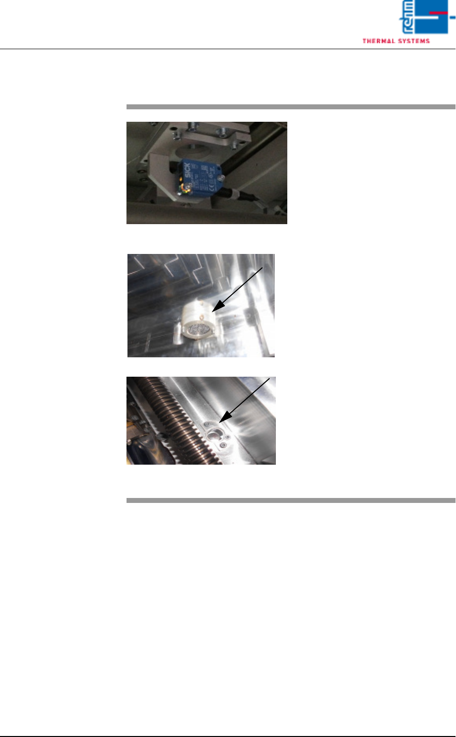
2.8.8 Sensors in the vacuum chamber
Fig. 2-53 Sensors for the vacuum chamber
Fig. 2-54 Sensors for the vacuum chamber
The sensor amplifiers for the vacu-
um unit are located at the back of
the system.
The sensor for the vacuum chamber
sits below the chamber. In the vacu-
um chamber, only the reflector and
sensor window are visible.
These sensors should be checked
from time to time to check the de-
gree of dirt.
Consumables, tools:
• Oven cleaner CF 1
• Cleaning cloths
• Vacuum cleaner
Procedure:
1. The transport system in the
vacuum chamber must be
moved apart.
2. Use a suitable cleaning cloth to
clean the viewing area of the
sensors as well as the vacuum
chamber.
3. Suck any dirt from the chamber
using a vacuum cleaner.
Vision XP+ VAC Page 39
2 Maintenance
2.8 Vacuum Unit
Operating Instructions
Version 1.5
2.8.9 Optical fibre sensors before and after the vacuum chamber
Fig. 2-55 Optical fibre sensors at the vacuum
chamber
Fig. 2-56 Optical fibre sensors at the vacuum
chamber
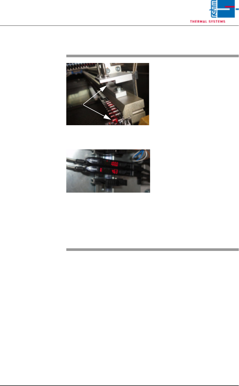
Optical fibre sensors are located be-
fore and after the vacuum chamber.
These optical fibre sensors are used
for PC board identification.
The specified as-is value of these
sensors is 4 000 digits (shown in
red).
Rehm Thermal Systems techni-
cians preset the switching threshold
to 2 700 digits (shown in yellow).
The PC board will be detected when
the threshold level is exceeded.
The contamination level is given as
a percentage. An alarm will in addi-
tion be triggered in the display
should this approach the threshold
level.
To continue proper operation, the
sensor should then be cleaned as
soon as possible, using an appropri-
ate cleaning agent.
The settings are based on Rehm
Thermal Systems experience.
Page 40 Vision XP+ VAC
2 Maintenance
2.8 Vacuum Unit
Operating Instructions
Version 1.5
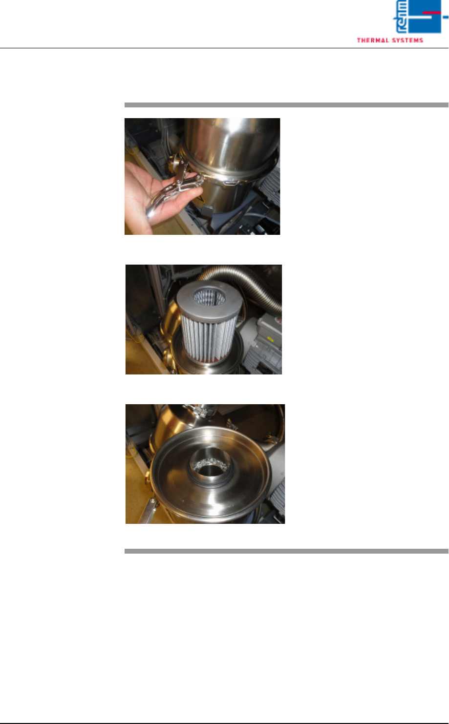
2.8.10 Vacuum pump filter
Fig. 2-57 Filter Vacuum pump
Fig. 2-58 Filter Vacuum pump
Fig. 2-59 Filter Vacuum pump
The filter container in front of the
vacuum pump must be opened from
time to time and the filter cleaned.
Consumbales, tool:
• Cleaning agent
• Cleaning cloth
• Cleaning bath
Procedure
1. The clamping ring of the filter
container must be opened.
The lid can be removed.
2. If the paper filter is dirty, it
must be replaced.
3. Lay the fabric filters in a suit-
able cleaning agent for clean-
ing.
4. After cleaning, put everything
back together and close the
clamping ring of the filter con-
tainer.