ServiceInstruction_Vision XP.pdf - 第54页
Page 50 Vision XP+ V AC 2 Maintenance 2.1 1 Condensate T rap Operating Instructions V ersion 1.5 2.1 1.5 Cleaning W ork at the Cooler Units (D) Fig. 2-7 7 Pulling Out the Cooler U nit Fig. 2-7 8 Pulling Out the Filter un…
Vision XP+ VAC Page 49
2 Maintenance
2.11 Condensate Trap
Operating Instructions
Version 1.5
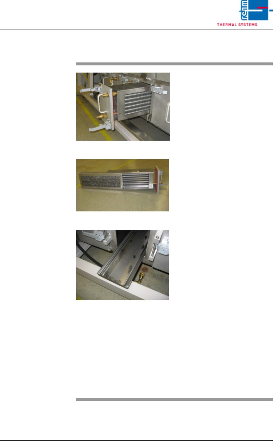
2.11.4 Cleaning Work at the Cooler Units (C)
Fig. 2-74 Pulling Out the Cooler Unit
Fig. 2-75 Pulling Out the Filter
Fig. 2-76 catch pan
The cooler units are located in the
bottom row of the condensate trap
(see item C in Fig. 2-74).
Consumable materials, tools:
• Oven cleaner
• Rags
• Rinsing bath
Procedure:
1. Open both locking levers and
pull out the cooler unit (see Fig.
2-75).
2. Pull the filter out of the cooler
unit and set it into the rinsing
bath.
3. Lift the cooler out of the cooler
unit and set it into the rinsing
bath as well.
4. Pull out the catch pan, empty it
an set it into the rinsing bath.
Caution!
The seals must protrude from
the bath. Otherwise they will be
damaged.
5. Clean the seals with Appropri-
ate cleaning agent and rags.
6. Clean the opening for the cooler
unit at the condensate trap with
oven cleaner and rags.
7. Reassemble cleaned parts and
insert them into the condensate
trap.
Note!
The quick couplings should be lubri-
cated occasionally, using suitable
lubricant, thereafter audibly click the
couplings back in.
Page 50 Vision XP+ VAC
2 Maintenance
2.11 Condensate Trap
Operating Instructions
Version 1.5
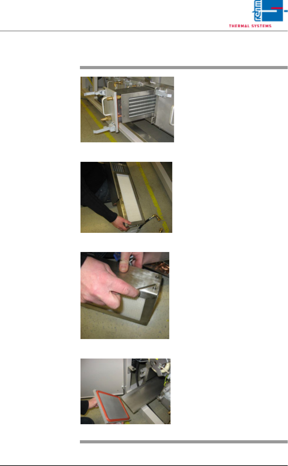
2.11.5 Cleaning Work at the Cooler Units (D)
Fig. 2-77 Pulling Out the Cooler Unit
Fig. 2-78 Pulling Out the Filter unit F9
Fig. 2-79 Metal Frame
Fig. 2-80 Drip pan
The cooler units are located in the
bottom row of the condensate trap.
Consumable materials, tools:
• Oven cleaner
• Rags
• Rinsing bath
• Allen wrench 2,5 mm
Procedure:
1. Open both locking levers and
pull out the cooler unit.
2. Pull the filter (F9) out of the
cooler unit.
3. Lift the cooler out of the cooler
unit and set it into the rinsing
bath as well
4. Open the metal frame of the fil-
ter (F9) with a 2,5 mm allen
wrench and replace the paper
filter (one-way).
Caution!
The seals must protrude from
the bath. Otherwise they will be
damaged.
5. Clean the seals with Appropri-
ate cleaning agent and rags.
6. Pull out the catch pan, empty it
an set it into the rinsing bath.
7. Clean the opening for the cooler
unit at the condensate trap with
oven cleaner and rags.
8. Reassemble cleaned parts and
insert them into the condensate
trap.
9. All connections restore.
Vision XP+ VAC Page 51
2 Maintenance
2.12 Pyrolysis
Operating Instructions
Version 1.5
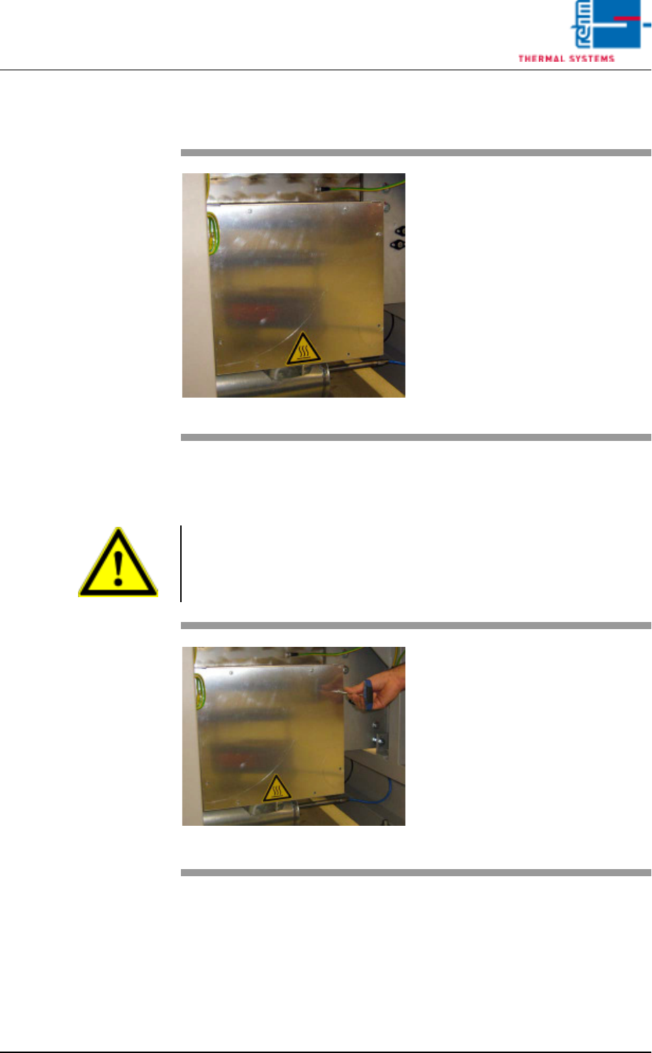
2.12 Pyrolysis
2.12.1 Replacing the Granulate
Fig. 2-81 Pyrolysis Unit
The pyrolysis unit is located at the
back of the system at the oven inlet.
Note!
The system must be cooled down before replacing the granulate, because
the granulate has a temperature of at least 500° C when the system is
running.
Fig. 2-82 Unscrewing the Door
Consumable materials, tools:
• Open-end wrench and hex key
• Granulate
• Cartridge seal
Procedure:
1. Remove the screws from the
cover and set them aside.
2. Loosen the nuts at the pyrolysis
unit and remove the cover.